
Introduction
The ESP32-CAM has become one of the most popular low-cost camera development boards for IoT, DIY smart home projects, and AI-powered vision systems. But in the previous years, a new wave of ESP32-CAM boards started appearing on the market that include built-in USB (CH340) and support not only the classic OV2640 sensor but also newer modules like the GC2541 / RHYX M21-45 from GalaxyCore. This module does not need an external programmer or a downloader board, so it is quite robust. In this post, I will outline how to use this ESP32-CAM module and outline the steps on how to test it.
Parts and Components Required
The following components are required to follow along with this post.
- ESP32-CAM CH340 Module – Amazon | AliExpress
- Windows Laptop – Amazon | AliExpress
- Raspberry Pi 5 – Amazon | AliExpress
Disclosure: These are affiliate links and I will earn small commissions to support my site when you buy through these links.
What is the ESP32-CAM CH340 Module?
Whether you are building a WiFi CCTV camera, an AI image recognition project, or experimenting with high-speed streaming (HTTP, WebSockets, or even raw UDP video), this new ESP32-CAM variant opens the door to more possibilities—especially with camera sensors beyond the classic OV2640.
In this beginner-friendly guide, we will explore:
- What makes the ESP32-CAM CH340 version different
- OV2640 vs GC2541 / RHYX M21-45 camera specifications
- How to set up the board without an external USB-TTL module
- How to start capturing images and streaming video
If you’re looking for an affordable yet powerful WiFi camera board that supports multiple image sensors, this guide will help you get started the right way.
ESP32-CAM Parts
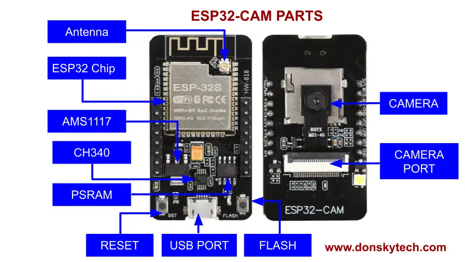
The image above shows the important parts of an ESP32-CAM CH340 module.
The back part of the module contains the following chips:
- ESP32s Chip – the main chip used by this module, which is a Dual-core Tensilica LX6. It provides integrated WiFi and Bluetooth support
- External Antenna Port – you can attach an external antenna to extend the WiFi range of this module. However, the ESP32-CAM CH340 module itself has a built-in Antenna etched into its PCB.
- AMS1117 – the module contains a voltage regulator that converts the incoming voltage to ESP32-compatible 3.3V. The recommended range to avoid overheating is 5.0V
- CH340 – this chip handles the USB to UART connection between your laptop and the ESP32 chip
- PSRAM – the PSRAM chip adds computing power to your ESP32. If needed, you can utilize this chip in your Arduino programs for better response.
- USB PORT – this is where you attach the microUSB cable to upload a sketch to your ESP32-CAM CH340 module
- FLASH Button – you click this button to set the ESP32-CAM into download or bootloader mode so that it can accept any uploaded sketch
- RESET button – this button is used to restart the ESP32-CAM CH340 module
The front face contains the camera and camera port module. Not labeled is the white Neopixel LED that lights up whenever you reset this module.
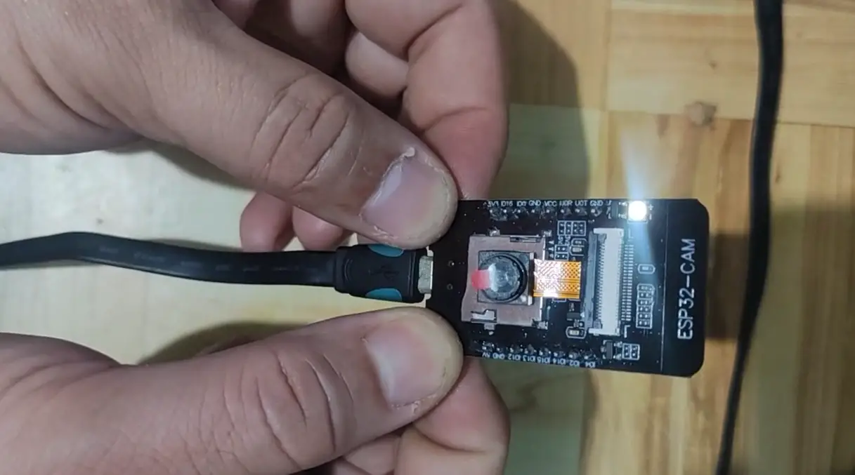
How to change the camera of the ESP32-CAM module?
If you want to change the camera pre-shipped with your module, gently click the black part of the camera port toward you with a sharp object or your nails. Once it pops up, remove the camera and replace it with another camera. Slid the new camera into its new position.
To lock it into position, gently push it inwards until it locks.
How to install the CH340 driver for ESP32-CAM?
This module uses the CH340 chip to communicate between the USB port of your laptop and the UART ESP32. You can install this driver by following the steps in this section: How to Install the CH340/CH341 Driver?
How to set the ESP32-CAM in Bootloader or Download mode? Fix for A fatal error occurred: Failed to connect to ESP32: No serial data received

If you try to upload any sketch into this module without setting this module into download or bootloader mode, then you will encounter this error.
Sketch uses 1065559 bytes (33%) of program storage space. Maximum is 3145728 bytes.
Global variables use 68140 bytes (20%) of dynamic memory, leaving 259540 bytes for local variables. Maximum is 327680 bytes.
esptool v5.1.0
Serial port COM11:
Connecting......................................
A fatal error occurred: Failed to connect to ESP32: No serial data received.
For troubleshooting steps visit: https://docs.espressif.com/projects/esptool/en/latest/troubleshooting.html

Failed uploading: uploading error: exit status 2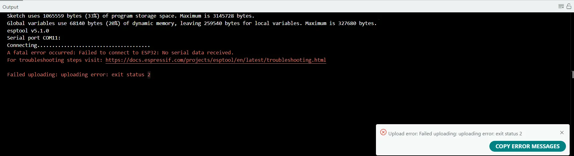
This means that the ESP32-CAM is not in bootloader or download mode, so it does not accept any sketch being uploaded.
To put this module in bootloader or download mode, do the following:
- Press the FLASH button and do not remove it yet.
- Press the RST momentarily and then release
- Unpress the FLASH button.
You should see the LED flash when you do this.
You can open your Arduino Serial Monitor to verify that the module is in Bootloader or Download mode

OV2640 VS GC2541 (RHYX M21-45) Camera?
Before, the OV2640 camera was the original camera that was pre-shipped with your ESP32-CAM module. However, when you order nowadays from AliExpress or Amazon, you will often receive this GC2145 model or the camera with the label RHYX M21-45.
The GC2145 or RHYX M21-45 label camera is often marketed by sellers as “China Domestic Camera“. Sellers usually tag this as a cheaper alternative to the OV2640 camera. Some sellers mislabel this as GC1245, but it is a different model altogether.

However, there are some major differences between the two, as noted by the image above.
Both OV2640 and GC2145 (RHYX M21-45) outputs RGB565, YUV, and RAW format. However, only the OV2640 has a built-in encoder that can directly output JPEG format.
These differences will greatly impact how you can program your ESP32-CAM, as will be shown later. If you want the GC2145 or RHYX M21-45 to output a JPEG, then you will need some help with the ESP32 chip by manually converting the RGB565 Raw output into JPEG format.
How to program ESP32-CAM CH340 with OV2640 Camera?
Prerequisites
Before we start programming your ESP32-CAM CH340 module, we first make sure that you are using the latest Arduino IDE. At this time, the latest version is 2.3.6. Next, in your board manager, make sure that you are using the latest ESP32 board.
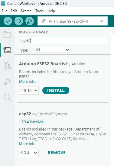
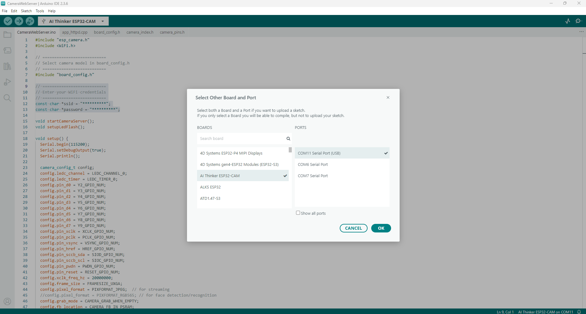
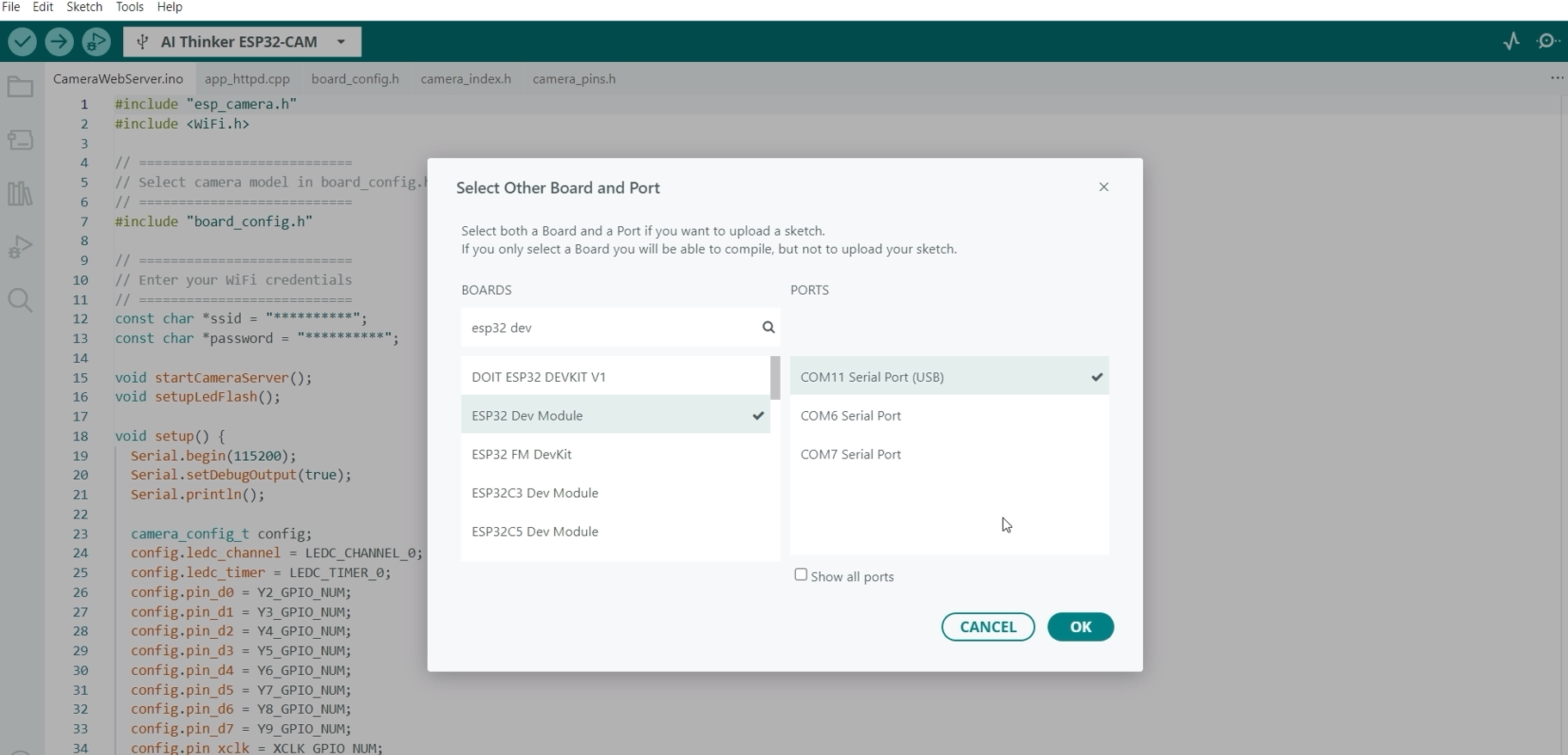
Next, we need to set the correct Board and Port. In the Board’s input box, locate the AI Thinker ESP32-CAM and the Ports to the COM port where your ESP32-CAM is assigned.
Your setup should look like the image below
Code
We will use the default CameraWebServer.ino sketch to test our ESP32-CAM with the CH340 built-in USB module.
- Click File -> Examples -> ESP32 -> Camera -> CameraWebServer
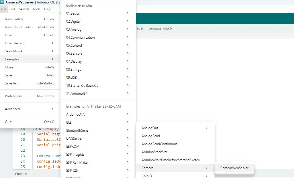
This should open the CameraWebServer.ino sketch in a new Window together with the different project files related to it.
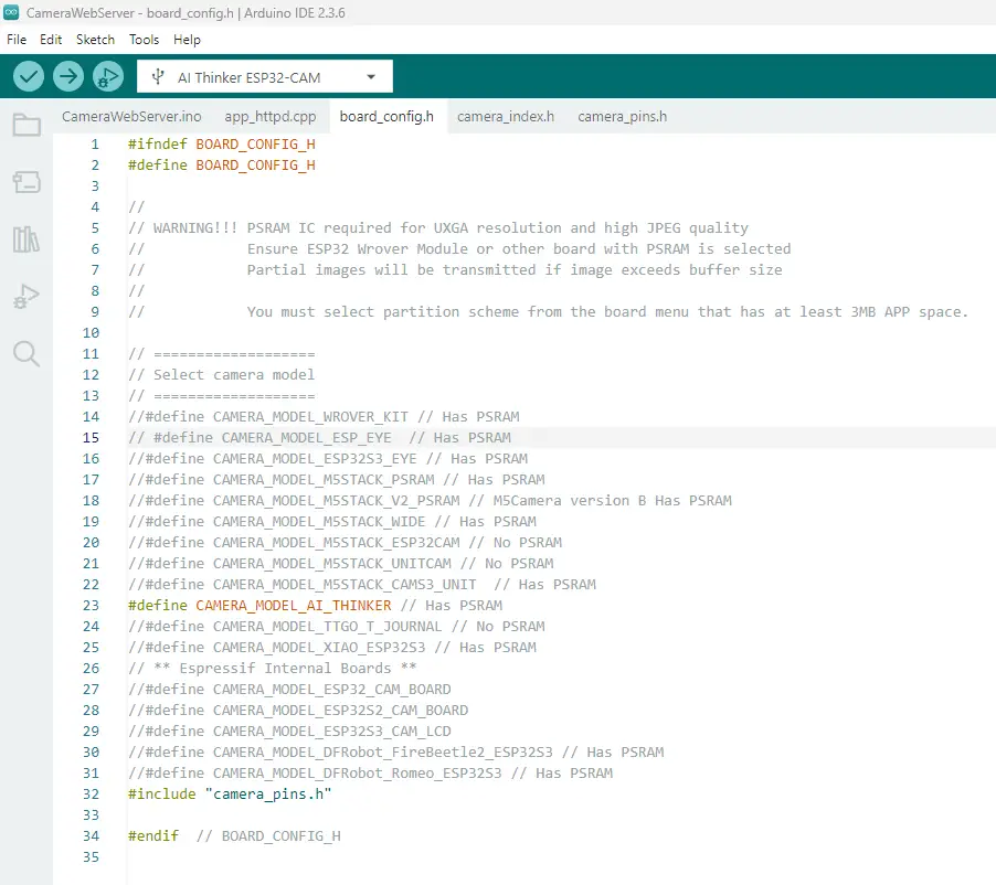
- Click the board_config.h and comment out the line below
#define CAMERA_MODEL_ESP_EYE // Has PSRAMAfter which, uncomment the following
#define CAMERA_MODEL_AI_THINKER // Has PSRAMYour board_config.h should look like the following
- Go back to the CameraWebServer.ino file and change the WiFi credentials
// ===========================
// Enter your WiFi credentials
// ===========================
const char *ssid = "**********";
const char *password = "**********";
Your code should look like this
#include "esp_camera.h"
#include <WiFi.h>

// ===========================
// Select camera model in board_config.h
// ===========================
#include "board_config.h"

// ===========================
// Enter your WiFi credentials
// ===========================
const char *ssid = "<YOUR_WIFI_SSID>";
const char *password = "<YOUR_WIFI_PASSWORD>";

void startCameraServer();
void setupLedFlash();

void setup() {
  Serial.begin(115200);
  Serial.setDebugOutput(true);
  Serial.println();

  camera_config_t config;
  config.ledc_channel = LEDC_CHANNEL_0;
  config.ledc_timer = LEDC_TIMER_0;
  config.pin_d0 = Y2_GPIO_NUM;
  config.pin_d1 = Y3_GPIO_NUM;
  config.pin_d2 = Y4_GPIO_NUM;
  config.pin_d3 = Y5_GPIO_NUM;
  config.pin_d4 = Y6_GPIO_NUM;
  config.pin_d5 = Y7_GPIO_NUM;
  config.pin_d6 = Y8_GPIO_NUM;
  config.pin_d7 = Y9_GPIO_NUM;
  config.pin_xclk = XCLK_GPIO_NUM;
  config.pin_pclk = PCLK_GPIO_NUM;
  config.pin_vsync = VSYNC_GPIO_NUM;
  config.pin_href = HREF_GPIO_NUM;
  config.pin_sccb_sda = SIOD_GPIO_NUM;
  config.pin_sccb_scl = SIOC_GPIO_NUM;
  config.pin_pwdn = PWDN_GPIO_NUM;
  config.pin_reset = RESET_GPIO_NUM;
  config.xclk_freq_hz = 20000000;
  config.frame_size = FRAMESIZE_UXGA;
  config.pixel_format = PIXFORMAT_JPEG;  // for streaming
  //config.pixel_format = PIXFORMAT_RGB565; // for face detection/recognition
  config.grab_mode = CAMERA_GRAB_WHEN_EMPTY;
  config.fb_location = CAMERA_FB_IN_PSRAM;
  config.jpeg_quality = 12;
  config.fb_count = 1;

  // if PSRAM IC present, init with UXGA resolution and higher JPEG quality
  //                      for larger pre-allocated frame buffer.
  if (config.pixel_format == PIXFORMAT_JPEG) {
    if (psramFound()) {
      config.jpeg_quality = 10;
      config.fb_count = 2;
      config.grab_mode = CAMERA_GRAB_LATEST;
    } else {
      // Limit the frame size when PSRAM is not available
      config.frame_size = FRAMESIZE_SVGA;
      config.fb_location = CAMERA_FB_IN_DRAM;
    }
  } else {
    // Best option for face detection/recognition
    config.frame_size = FRAMESIZE_240X240;
#if CONFIG_IDF_TARGET_ESP32S3
    config.fb_count = 2;
#endif
  }

#if defined(CAMERA_MODEL_ESP_EYE)
  pinMode(13, INPUT_PULLUP);
  pinMode(14, INPUT_PULLUP);
#endif

  // camera init
  esp_err_t err = esp_camera_init(&config);
  if (err != ESP_OK) {
    Serial.printf("Camera init failed with error 0x%x", err);
    return;
  }

  sensor_t *s = esp_camera_sensor_get();
  // initial sensors are flipped vertically and colors are a bit saturated
  if (s->id.PID == OV3660_PID) {
    s->set_vflip(s, 1);        // flip it back
    s->set_brightness(s, 1);   // up the brightness just a bit
    s->set_saturation(s, -2);  // lower the saturation
  }
  // drop down frame size for higher initial frame rate
  if (config.pixel_format == PIXFORMAT_JPEG) {
    s->set_framesize(s, FRAMESIZE_QVGA);
  }

#if defined(CAMERA_MODEL_M5STACK_WIDE) || defined(CAMERA_MODEL_M5STACK_ESP32CAM)
  s->set_vflip(s, 1);
  s->set_hmirror(s, 1);
#endif

#if defined(CAMERA_MODEL_ESP32S3_EYE)
  s->set_vflip(s, 1);
#endif

// Setup LED FLash if LED pin is defined in camera_pins.h
#if defined(LED_GPIO_NUM)
  setupLedFlash();
#endif

  WiFi.begin(ssid, password);
  WiFi.setSleep(false);

  Serial.print("WiFi connecting");
  while (WiFi.status() != WL_CONNECTED) {
    delay(500);
    Serial.print(".");
  }
  Serial.println("");
  Serial.println("WiFi connected");

  startCameraServer();

  Serial.print("Camera Ready! Use 'http://");
  Serial.print(WiFi.localIP());
  Serial.println("' to connect");
}

void loop() {
  // Do nothing. Everything is done in another task by the web server
  delay(10000);
}
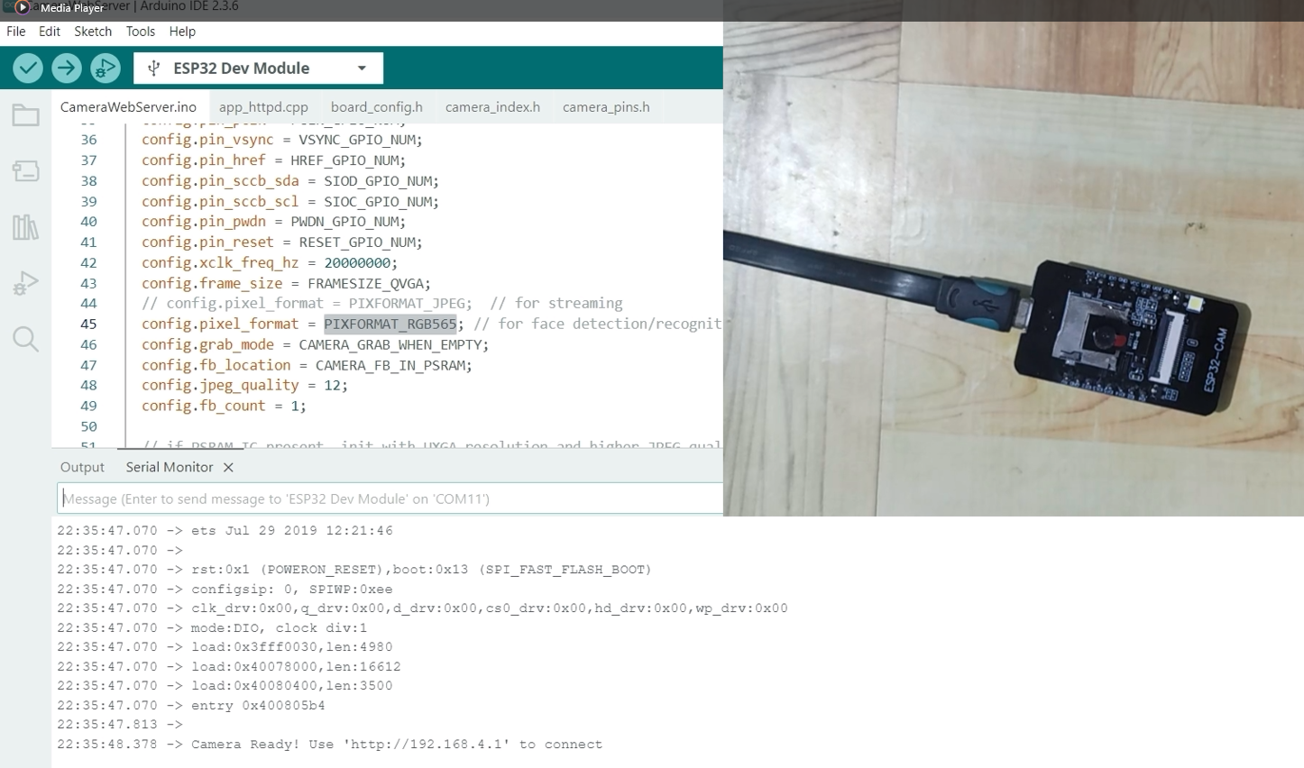
- Set your ESP32-CAM CH340 module with OV2640 camera into bootloader or download mode, and then upload this sketch. After the upload has finished, click the RESET button. Your output should look like the image below.
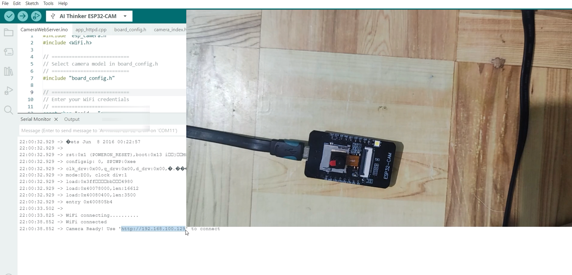
- Next, take note and copy the following IP address shown on the Serial Monitor, and open a new web browser. Paste the IP Address, and you should see the following Web Application Displayed. Click the Start Stream button below, and you should see the following Video Stream coming from your ESP32-CAM.
You can try to click the Get Still Button to capture a Camera Image from your ESP32-CAM.
If you are seeing a video stream, then you have successfully set up your ESP32-CAM CH340 model. We will discuss next on how to program the ESP32-CAM CH340 with GC2541 or RHYX M21-45 Camera.
How to program ESP32-CAM CH340 with GC2541 or RHYX M21-45 Camera?
Camera init failed with error 0x106
This error will pop up if you follow the steps above and upload the same sketch to an ESP32-CAM with a GC2541 or RHYX M21-45 camera. The exact error that will be shown in your camera will be
E (475) camera: JPEG format is not supported on this sensor
Camera init failed with error 0x106
As I have mentioned in the earlier section, this camera module cannot output JPEG as it does not have the necessary encoder to output it. The ideal output for this camera module is RGB565, and that is what we are going to do in this section.
Prerequisites
First, we need to set the Board and Port for this ESP32-CAM with GC2541 (RHYX M21-45) to the ESP32 Dev Module.
This will allow us to set extra configurations on the ESP32 modules, like enabling the PSRAM.
Code
To program the ESP32-CAM with a GC2145 or RHYX M21-45 camera, follow the steps below.
- Click File -> Examples -> ESP32 -> Camera -> CameraWebServer
- Click the board_config.h and comment out the line below, and make sure that it looks like this.
#ifndef BOARD_CONFIG_H
#define BOARD_CONFIG_H

//
// WARNING!!! PSRAM IC required for UXGA resolution and high JPEG quality
//            Ensure ESP32 Wrover Module or other board with PSRAM is selected
//            Partial images will be transmitted if image exceeds buffer size
//
//            You must select partition scheme from the board menu that has at least 3MB APP space.

// ===================
// Select camera model
// ===================
//#define CAMERA_MODEL_WROVER_KIT // Has PSRAM
// #define CAMERA_MODEL_ESP_EYE  // Has PSRAM
//#define CAMERA_MODEL_ESP32S3_EYE // Has PSRAM
//#define CAMERA_MODEL_M5STACK_PSRAM // Has PSRAM
//#define CAMERA_MODEL_M5STACK_V2_PSRAM // M5Camera version B Has PSRAM
//#define CAMERA_MODEL_M5STACK_WIDE // Has PSRAM
//#define CAMERA_MODEL_M5STACK_ESP32CAM // No PSRAM
//#define CAMERA_MODEL_M5STACK_UNITCAM // No PSRAM
//#define CAMERA_MODEL_M5STACK_CAMS3_UNIT  // Has PSRAM
#define CAMERA_MODEL_AI_THINKER // Has PSRAM
//#define CAMERA_MODEL_TTGO_T_JOURNAL // No PSRAM
//#define CAMERA_MODEL_XIAO_ESP32S3 // Has PSRAM
// ** Espressif Internal Boards **
//#define CAMERA_MODEL_ESP32_CAM_BOARD
//#define CAMERA_MODEL_ESP32S2_CAM_BOARD
//#define CAMERA_MODEL_ESP32S3_CAM_LCD
//#define CAMERA_MODEL_DFRobot_FireBeetle2_ESP32S3 // Has PSRAM
//#define CAMERA_MODEL_DFRobot_Romeo_ESP32S3 // Has PSRAM
#include "camera_pins.h"

#endif  // BOARD_CONFIG_H
- Open the CameraWebServer.ino file and paste the following code.
#include "esp_camera.h"
#include <WiFi.h>

// ===========================
// Select camera model in board_config.h
// ===========================
#include "board_config.h"

// ===========================
// Setup SOFTAP for the ESP32-CAM
// ===========================
const char *ssid = "ESP32CAM_SOFTAP";
const char *password = "Testing123";

void startCameraServer();
void setupLedFlash();

void setup() {
  Serial.begin(115200);
  Serial.setDebugOutput(true);
  Serial.println();

  camera_config_t config;
  config.ledc_channel = LEDC_CHANNEL_0;
  config.ledc_timer = LEDC_TIMER_0;
  config.pin_d0 = Y2_GPIO_NUM;
  config.pin_d1 = Y3_GPIO_NUM;
  config.pin_d2 = Y4_GPIO_NUM;
  config.pin_d3 = Y5_GPIO_NUM;
  config.pin_d4 = Y6_GPIO_NUM;
  config.pin_d5 = Y7_GPIO_NUM;
  config.pin_d6 = Y8_GPIO_NUM;
  config.pin_d7 = Y9_GPIO_NUM;
  config.pin_xclk = XCLK_GPIO_NUM;
  config.pin_pclk = PCLK_GPIO_NUM;
  config.pin_vsync = VSYNC_GPIO_NUM;
  config.pin_href = HREF_GPIO_NUM;
  config.pin_sccb_sda = SIOD_GPIO_NUM;
  config.pin_sccb_scl = SIOC_GPIO_NUM;
  config.pin_pwdn = PWDN_GPIO_NUM;
  config.pin_reset = RESET_GPIO_NUM;
  config.xclk_freq_hz = 20000000;
  config.frame_size = FRAMESIZE_QVGA;
  // config.pixel_format = PIXFORMAT_JPEG;  // for streaming
  config.pixel_format = PIXFORMAT_RGB565; // for face detection/recognition
  config.grab_mode = CAMERA_GRAB_WHEN_EMPTY;
  config.fb_location = CAMERA_FB_IN_PSRAM;
  config.jpeg_quality = 12;
  config.fb_count = 1;

  // if PSRAM IC present, init with UXGA resolution and higher JPEG quality
  //                      for larger pre-allocated frame buffer.
  if (config.pixel_format == PIXFORMAT_RGB565) {
    if (psramFound()) {
      config.jpeg_quality = 10;
      config.fb_count = 2;
      config.grab_mode = CAMERA_GRAB_LATEST;
    } else {
      // Limit the frame size when PSRAM is not available
      config.frame_size = FRAMESIZE_SVGA;
      config.fb_location = CAMERA_FB_IN_DRAM;
    }
  } else {
    // Best option for face detection/recognition
    config.frame_size = FRAMESIZE_240X240;
#if CONFIG_IDF_TARGET_ESP32S3
    config.fb_count = 2;
#endif
  }

#if defined(CAMERA_MODEL_ESP_EYE)
  pinMode(13, INPUT_PULLUP);
  pinMode(14, INPUT_PULLUP);
#endif

  // camera init
  esp_err_t err = esp_camera_init(&config);
  if (err != ESP_OK) {
    Serial.printf("Camera init failed with error 0x%x", err);
    return;
  }

  sensor_t *s = esp_camera_sensor_get();
  // initial sensors are flipped vertically and colors are a bit saturated
  if (s->id.PID == OV3660_PID) {
    s->set_vflip(s, 1);        // flip it back
    s->set_brightness(s, 1);   // up the brightness just a bit
    s->set_saturation(s, -2);  // lower the saturation
  }
  // drop down frame size for higher initial frame rate
  if (config.pixel_format == PIXFORMAT_RGB565) {
    s->set_framesize(s, FRAMESIZE_QVGA);
  }

#if defined(CAMERA_MODEL_M5STACK_WIDE) || defined(CAMERA_MODEL_M5STACK_ESP32CAM)
  s->set_vflip(s, 1);
  s->set_hmirror(s, 1);
#endif

#if defined(CAMERA_MODEL_ESP32S3_EYE)
  s->set_vflip(s, 1);
#endif

// Setup LED FLash if LED pin is defined in camera_pins.h
#if defined(LED_GPIO_NUM)
  setupLedFlash();
#endif

  WiFi.softAP(ssid, password);
  // WiFi.setSleep(false);

  // Serial.print("WiFi connecting");
  // while (WiFi.status() != WL_CONNECTED) {
  //   delay(500);
  //   Serial.print(".");
  // }
  // Serial.println("");
  // Serial.println("WiFi connected");

  startCameraServer();

  Serial.print("Camera Ready! Use 'http://");
  Serial.print(WiFi.softAPIP());
  Serial.println("' to connect");
}

void loop() {
  // Do nothing. Everything is done in another task by the web server
  delay(10000);
}
I made some changes to the original code to make it work with the ESP32-CAM CH340 model with a GC2145 (RHYX M21-45) Camera. Below is the list of changes:
// ===========================
// Setup SOFTAP for the ESP32-CAM
// ===========================
const char *ssid = "ESP32CAM_SOFTAP";
const char *password = "Testing123";
Instead of our ESP32-CAM connecting to our WiFi, we will configure it in soft AP mode so that it will act as our router.
  config.frame_size = FRAMESIZE_QVGA;
  // config.pixel_format = PIXFORMAT_JPEG;  // for streaming
  config.pixel_format = PIXFORMAT_RGB565; // for face detection/recognition
Next, we set the config.frame_size = FRAMESIZE_QVGA to make the image smaller. We also set the config.pixel_format = PIXFORMAT_RGB565 since it does not have a built-in JPEG encoder.
  // if PSRAM IC present, init with UXGA resolution and higher JPEG quality
  //                      for larger pre-allocated frame buffer.
  if (config.pixel_format == PIXFORMAT_RGB565) {
    if (psramFound()) {
      config.jpeg_quality = 10;
      config.fb_count = 2;
      config.grab_mode = CAMERA_GRAB_LATEST;
    } else {
      // Limit the frame size when PSRAM is not available
      config.frame_size = FRAMESIZE_SVGA;
      config.fb_location = CAMERA_FB_IN_DRAM;
    }
  } else {
    // Best option for face detection/recognition
    config.frame_size = FRAMESIZE_240X240;
#if CONFIG_IDF_TARGET_ESP32S3
    config.fb_count = 2;
#endif
  }
After, we take advantage of the PSRAM to increase the quality and other settings.
  // drop down frame size for higher initial frame rate
  if (config.pixel_format == PIXFORMAT_RGB565) {
    s->set_framesize(s, FRAMESIZE_QVGA);
  }
We also decrease the framesize to QVGA format.
  WiFi.softAP(ssid, password);
  // WiFi.setSleep(false);

  // Serial.print("WiFi connecting");
  // while (WiFi.status() != WL_CONNECTED) {
  //   delay(500);
  //   Serial.print(".");
  // }
  // Serial.println("");
  // Serial.println("WiFi connected");

  startCameraServer();

  Serial.print("Camera Ready! Use 'http://");
  Serial.print(WiFi.softAPIP());
  Serial.println("' to connect");
As mentioned above, we will configure the ESP32-CAM in softAP mode so that it will act as our router. We will then configure our router to connect to the ESP32-CAM Access Point.
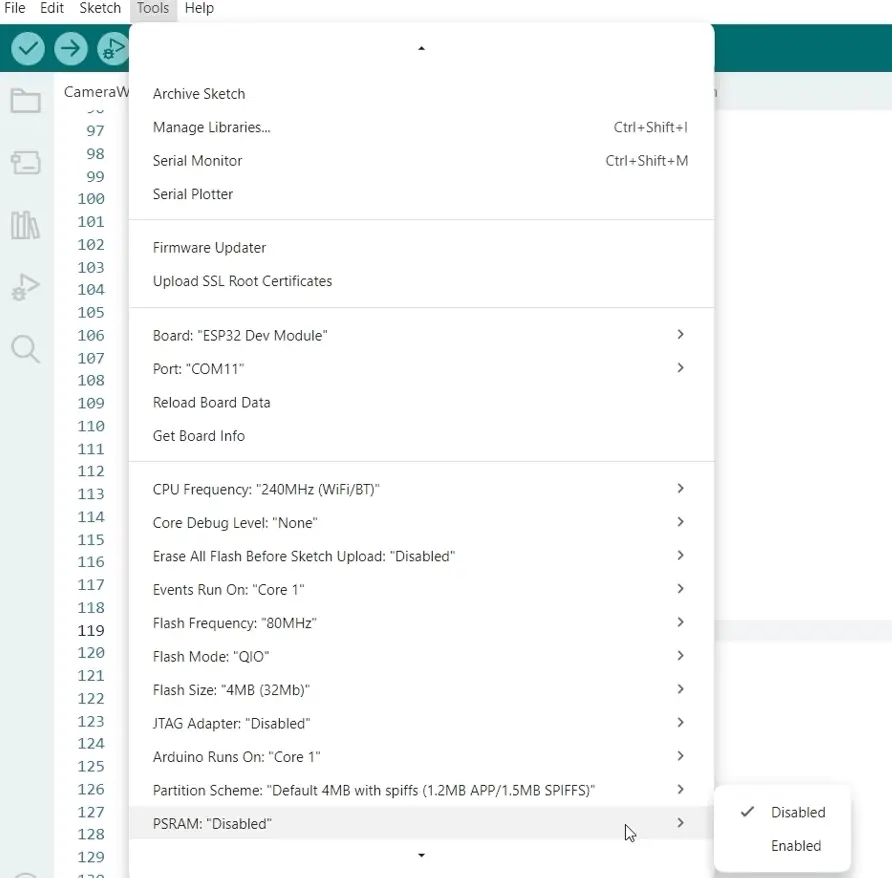
Next, we need to set some module configurations, like enabling the PSRAM. To do this, click Tools -> PSRAM, then select Enabled
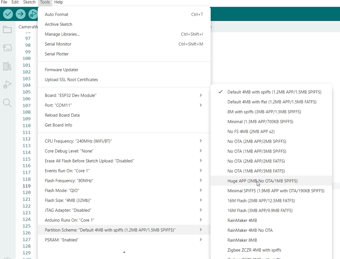
Set also the Partition Scheme as Huge APP (3MB No OTA/1MB SPIFFS)
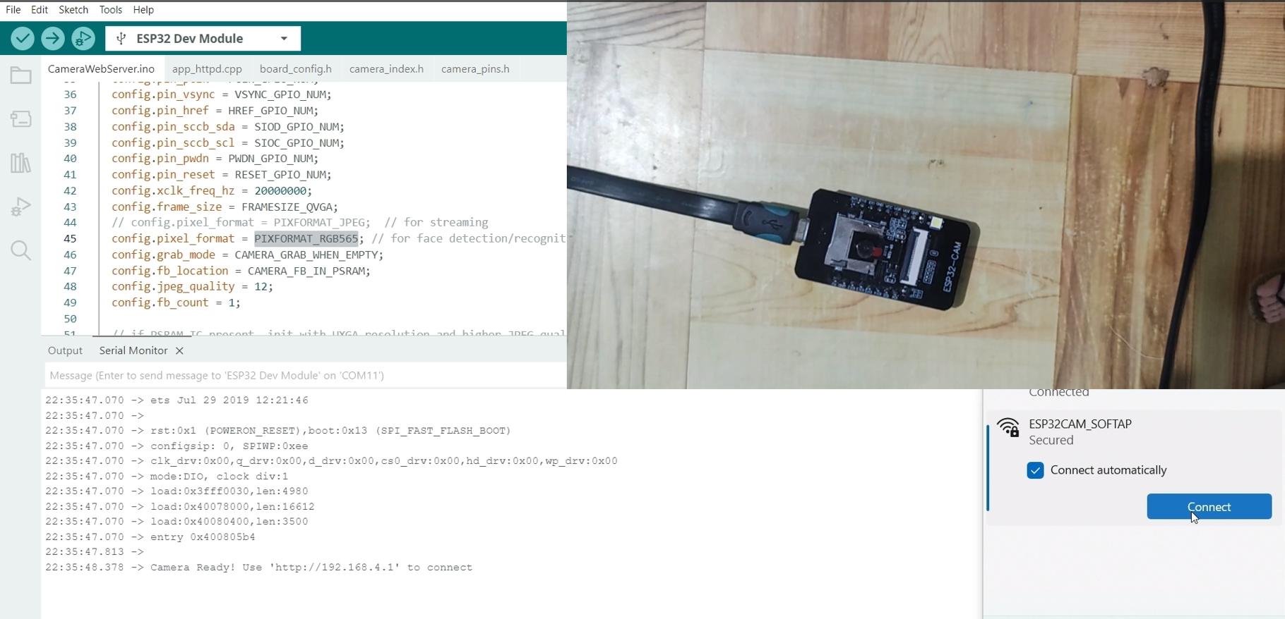
After doing all of this, set your ESP32-CAM into bootloader or download mode, then upload this sketch. Open your Serial monitor and click the Reset button afterwards to restart your ESP32-CAM. You should see an image similar to the one below.
Take note of the assigned IP Address as we will be using it in the next step.
Open your laptop’s WiFi connection and search for the WiFi named ESP32CAM_SOFTAP
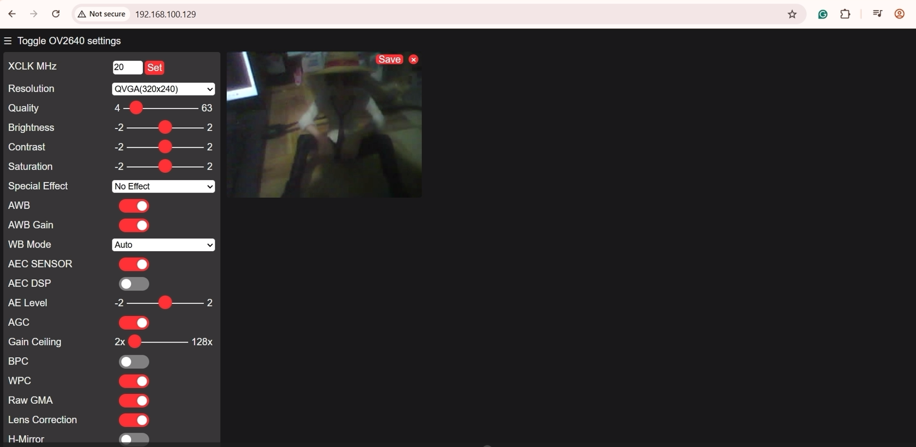
Open a new browser and paste the assigned IP Address. This would open the web application similar to the OV2640 camera setup, but is now using the GC2145 (RHYX M21-45) Camera. Click the Start Stream button, and you should see your browser showing the video stream.
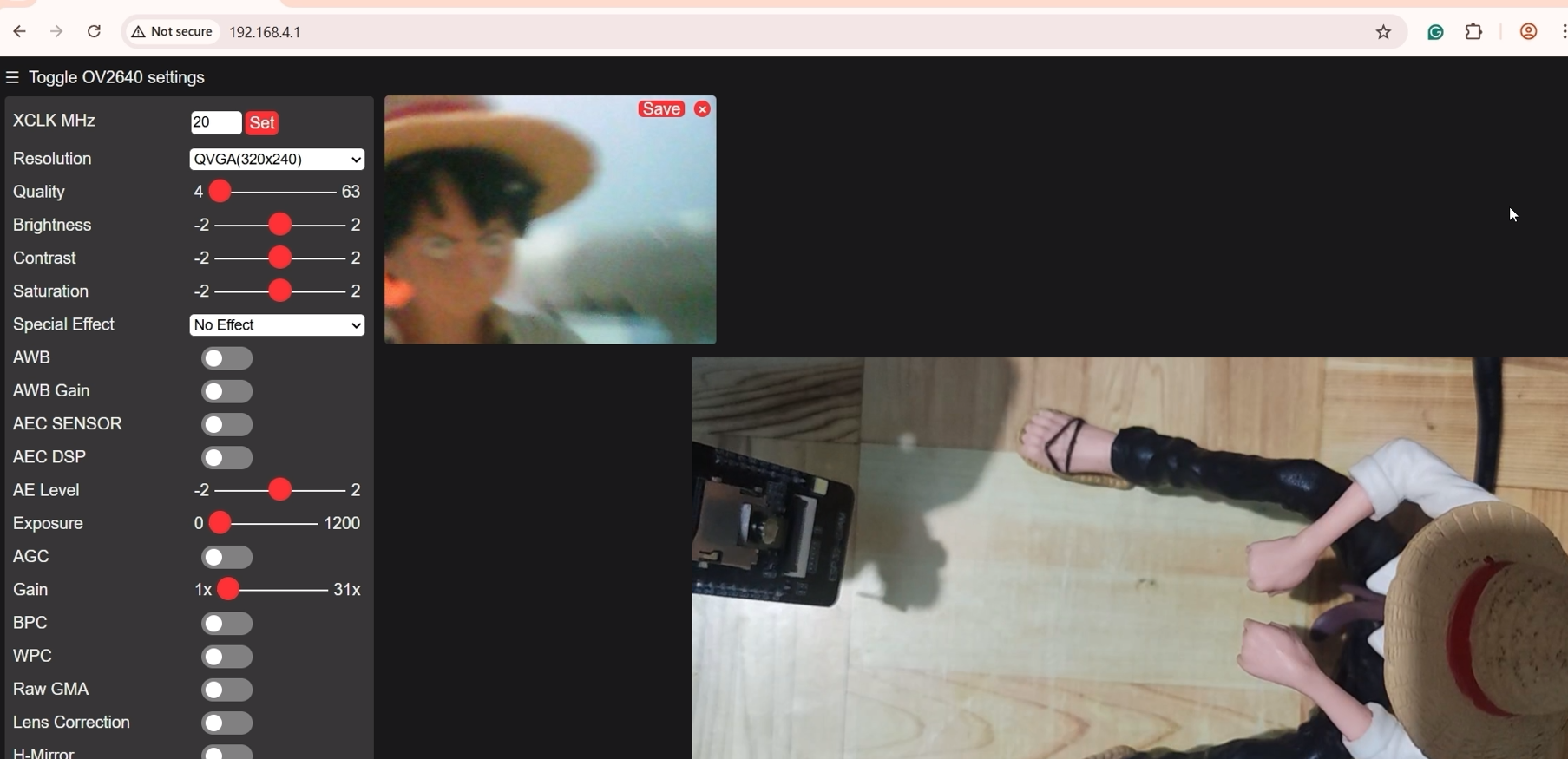
If you are seeing this video stream, then congratulations, as you have tested your successfully set up and tested your ESP32-CAM CH340 model with a GC2145 (RHYX M21-45) Camera.
A note about the Video Stream Performance
There is a significant performance difference if you compare the output of the video stream between the OV2640 and GC2145 (RHYX M21-45). The exact reason is that we are displaying the RGB565 raw output in a browser so there are some lags or delay.
What’s next?
There are lots of project
Final Thoughts
This post outlines the steps on how to set up and test your ESP32-CAM CH340 model with an OV2640 or GC2145 (RHYX M21-35) Camera. I have explained the difference between the two cameras and how it affects the way you program them. I have shared with you the steps on how to upload sketches to test the video streaming capabilities of your module.
I hope you learned something. Happy exploring!
Leave a Reply