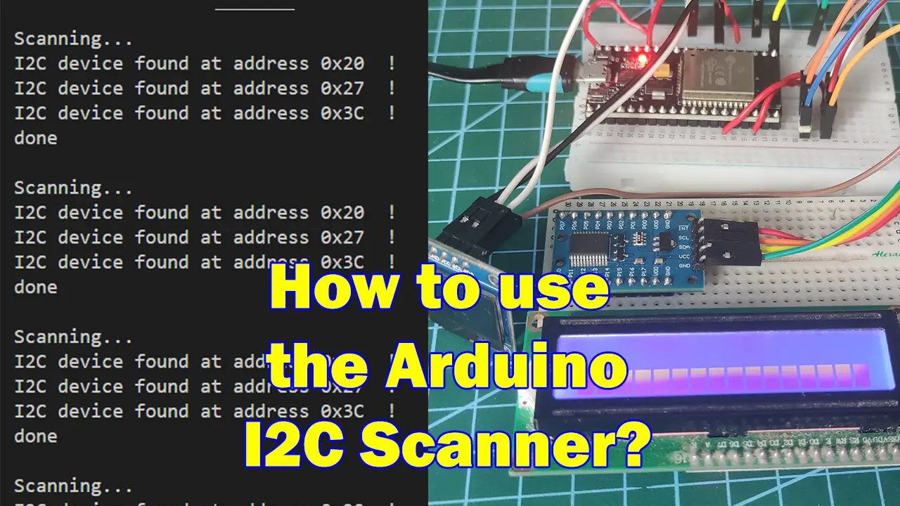
Introduction
If you are working on an epic Internet of Things (IoT) project and you received an I2C sensor/device then chances are you might be excited to write code to retrieve the readings. Only to find out that it does not work or it is not communicating with your Arduino code. This post will show you how to use the Arduino I2C scanner sketch (i2c_scanner) and why you need it before you start programming.
If you want to see this post in video format then please see the below video or watch it on my YouTube channel.
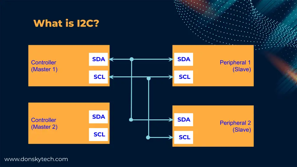
What is I2C?
I2C or Inter-Integrated Circuit (pronounced as eye-squared C) is one of the popular communication protocols used to allow multiple sensors to communicate with your microcontrollers. I2C uses two wires which are called the SCL (Serial Clock) and SDA (Serial Data). Well, technically speaking it is still 4 wires as you need the GND and VCC pins to provide power. It can support multiple controllers(masters) and multiple devices or peripherals(slaves ). This ability to connect multiple sensors on a single bus (SDA/SCL combination) makes it ideal for any Arduino-powered circuits especially if you are controlling multiple sensors or components.
We will not be discussing in detail how this I2C protocol works in this post but you can check the Wikipedia link if you want to know more. As an aside, there are other protocols widely used in Arduino-based projects such as the SPI, Serial or UART, and One-Wire but that is beyond the scope of this post.
What is I2C Address?
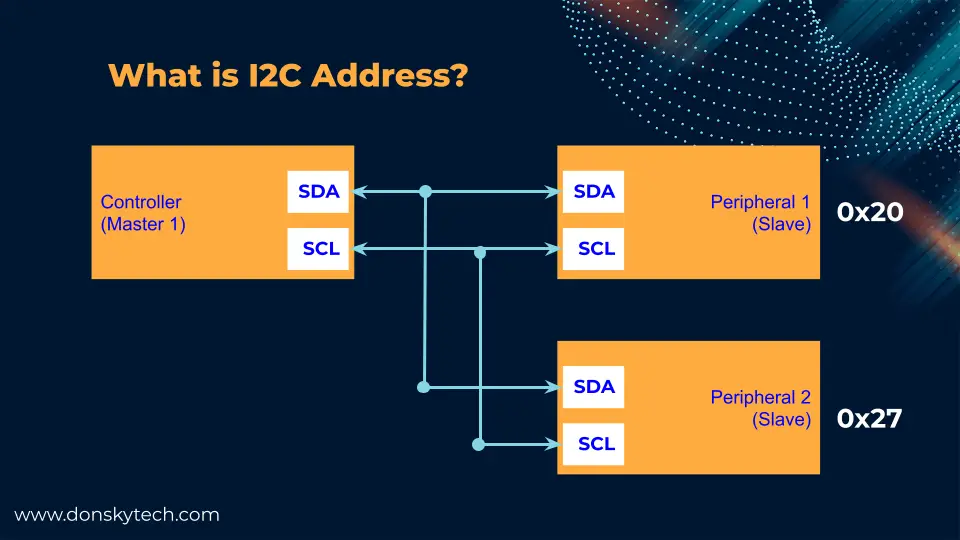
Because of the I2C’s ability to connect multiple devices along its bus (or two wires) then the controller or our Arduino-powered board needs to somehow know where to send data. This is what an I2C address is all about and this should be a distinct address that ranges from 0 to 127 (0 to 0x7F in Hex) that will uniquely identify each sensor connected to your controller.
Usually, manufacturers of sensors and other I2C components have a default I2C address assigned for their sensors out of the box. The problem with I2C is that you cannot connect two sensors/devices on the same SDA/SCL pins with the same I2C address. But fortunately, these sensors have the ability to change the default I2C address by soldering some jumper components. Check your sensor data sheets on how to do this.
How to connect multiple I2C devices in Arduino?
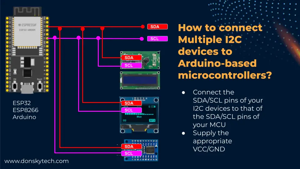
The usual question that I received is how they can connect multiple I2C devices or sensors on their Arduino-powered microcontrollers such as the Arduino Uno, ESP8266, or ESP32. If you are new to Arduino programming then you might be surprised that you only just need to connect the SDA/SCL combinations of your sensors to the same I2C pins of your microcontroller.
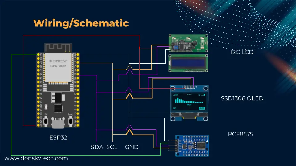
In the image above, the ESP32 SDA/SCL pins (GPIO21/GPIO22) are connected in parallel to all my I2C sensors and devices. As I have mentioned, this would work only if each sensor or device has a unique I2C address.
What is the Arduino I2C Scanner or i2c_scanner?
So where does the Arduino I2C Scanner or the i2c_scanner come into the picture?
During your Arduino project development, you would definitely run across these steps:
- Look for the appropriate sensor or devices for your project
- Wire the sensors to your Arduino-powered microcontroller
- Look for a suitable library to drive your sensor/device
- Create your program and check the sensor readings
But upon running your program you have probably run into the issues below:
- Why can’t I retrieve any sensor readings from my sensor?
- Why can’t I display any messages on my I2C LCD Display or SSD1306 OLED?
The reason is that you miss one crucial step between steps 3 and 4 and I would admit that I fall into this trap also. I often get too excited to test my sensor and see the output that I almost forgot to check if my Microcontroller detected it in my I2C bus.
- Look for the appropriate sensor or devices for your project
- Wire the sensors to your Arduino-powered microcontroller
- Look for a suitable library to drive your sensor/device
- Check if your microcontroller detected your I2C device/sensor
- Create your program and check the sensor readings
So how do we check if our Arduino-powered microcontroller indeed detects our i2C device/sensor? That is what the Arduino I2C scanner or i2c_scanner is all about. This is just actually a simple Arduino sketch that you can run that would scan all I2C device addresses that are connected to the I2C SDA/SCL bus lines. Let us now go to some code.
Prerequisites
I am using PlatformIO IDE in running this project but you can use your Arduino IDE if you like as we will just be running a simple sketch.
Related Content:
PlatformIO Tutorial for Arduino Development
Parts/Components Required
The followings are the components/parts required to follow along with this post.
- ESP32 (I used NodeMCU ESP32s) – Amazon | AliExpress | Bangood
- or ESP8266 – Amazon | AliExpress | Bangood
- SSD1306 OLED – Amazon | AliExpress | Bangood
- I2C LCD Display – Amazon | AliExpress | Bangood
- PCF8575 – Amazon | AliExpress
- Breadboard – Amazon | AliExpress | Bangood
- Connecting Wires – Amazon | AliExpress | Bangood
Disclosure: These are affiliate links and I will earn small commissions to support my site when you buy through these links.
Wiring/Schematic
Below is how I wired my ESP32 with several I2C devices.
I have connected 3 I2C-enabled sensors/devices which are an I2C LCD Display, SSD1306 OLED, and a PCF8575 GPIO Port expander module.
This table would show the exact connections for each component.
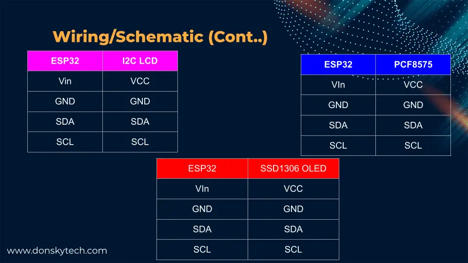
If you are using another microcontroller such as the Arduino Uno or ESP8266 then simply change the wiring to the hardware SDA/SCL pins of your microcontroller.
Code
Below is the Arduino sketch that would scan all the I2C devices connected to your microcontroller. I have copied the following program from the official Arduino site just for reference only in this post.
 // This gist was copied from the Arduino site and place here just for reference

// --------------------------------------
// i2c_scanner
//
// Version 1
//    This program (or code that looks like it)
//    can be found in many places.
//    For example on the Arduino.cc forum.
//    The original author is not know.
// Version 2, Juni 2012, Using Arduino 1.0.1
//     Adapted to be as simple as possible by Arduino.cc user Krodal
// Version 3, Feb 26  2013
//    V3 by louarnold
// Version 4, March 3, 2013, Using Arduino 1.0.3
//    by Arduino.cc user Krodal.
//    Changes by louarnold removed.
//    Scanning addresses changed from 0...127 to 1...119,
//    according to the i2c scanner by Nick Gammon
//    https://www.gammon.com.au/forum/?id=10896
// Version 5, March 28, 2013
//    As version 4, but address scans now to 127.
//    A sensor seems to use address 120.
// Version 6, November 27, 2015.
//    Added waiting for the Leonardo serial communication.
//
//
// This sketch tests the standard 7-bit addresses
// Devices with higher bit address might not be seen properly.
//

#include <Wire.h>


void setup()
{
  Wire.begin();

  Serial.begin(9600);
  while (!Serial);             // Leonardo: wait for serial monitor
  Serial.println("\nI2C Scanner");
}


void loop()
{
  byte error, address;
  int nDevices;

  Serial.println("Scanning...");

  nDevices = 0;
  for(address = 1; address < 127; address++ )
  {
    // The i2c_scanner uses the return value of
    // the Write.endTransmisstion to see if
    // a device did acknowledge to the address.
    Wire.beginTransmission(address);
    error = Wire.endTransmission();

    if (error == 0)
    {
      Serial.print("I2C device found at address 0x");
      if (address<16)
        Serial.print("0");
      Serial.print(address,HEX);
      Serial.println("  !");

      nDevices++;
    }
    else if (error==4)
    {
      Serial.print("Unknown error at address 0x");
      if (address<16)
        Serial.print("0");
      Serial.println(address,HEX);
    }
  }
  if (nDevices == 0)
    Serial.println("No I2C devices found\n");
  else
    Serial.println("done\n");

  delay(5000);           // wait 5 seconds for next scan
}
What the code is doing is scanning all I2C devices connected to the SDA/SCL lines of your microcontroller. If one or more are active then it should display the following on your terminal. In my particular circuit that has 3 I2C devices connected then the Arduino I2C Scanner is printing me the address of my I2C devices.
Scanning...
I2C device found at address 0x20  !
I2C device found at address 0x27  !
I2C device found at address 0x3C  !
done
Issues
No I2C devices found
If you run into this problem then chances are that this could just be a wiring problem so tighten the connection on your breadboard. If it still fails then try a different microcontroller and if it still does not work then your sensor/device might be broken so find another one.
Wrap Up
So the next time you received your I2C sensor or device then don’t get excited about wiring and running your program and not being able to make it work. You always need to verify first that your Microcontroller is able to communicate properly with your sensor/device by running the Arduino I2C scanner.
This is such a simple step but often gets discarded so I have written a simple post about it.
I hope you learned something! Happy exploring!
Leave a Reply