Introduction
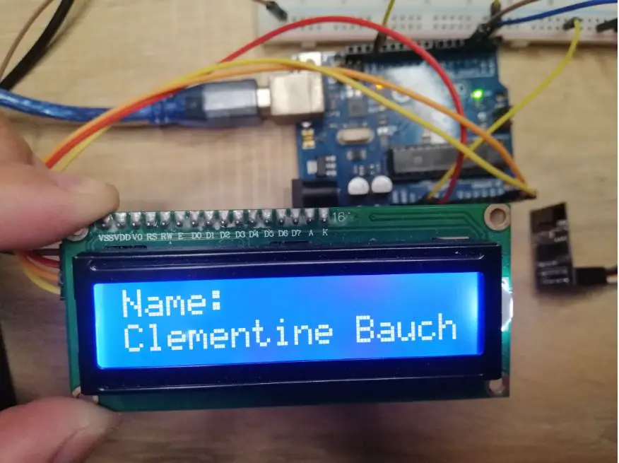
In this article, we are going to discuss how to connect your Arduino Uno board to your WiFi and retrieve data from the Internet that you can process in your Arduino Project. We will be using the ESP8266 ESP-01 module to connect to our wifi and retrieve data from our online source. We are going to display the following data on our LCD screen that is controlled by Arduino.
If you want to see a video demo presentation of this post then please see below or watch it on my YouTube channel.
Parts/Components Required
The followings are the components and tools required in order to follow along with this post.
- Arduino Uno – Amazon | AliExpress | Bangood
- ESP8266 ESP-01 – Amazon | AliExpress | Bangood
- (16 x 2)LCD – Amazon | AliExpress | Bangood
- Breadboard – Amazon | AliExpress | Bangood
- Connecting Wires – Amazon | AliExpress | Bangood
Disclosure: These are affiliate links and I will earn small commissions to support my site when you buy through these links.
How can Arduino Uno connect to WiFi?
The Arduino Uno itself does not have any WiFi connectivity features so we are going to use this ESP-01 as our bridge to connect to the internet. The ESP8266 ESP-01 is a small module Microcontroller with a WiFi microchip that can allow you to connect to the internet and execute TCP/IP connections.
This is a very cheap module compared to using a WiFi Ethernet Shield and can functionally run by itself. In fact, if we use other ESP8266 variants like the NodeMCU ESP-12E we can actually ditch the Arduino and just use it by itself.
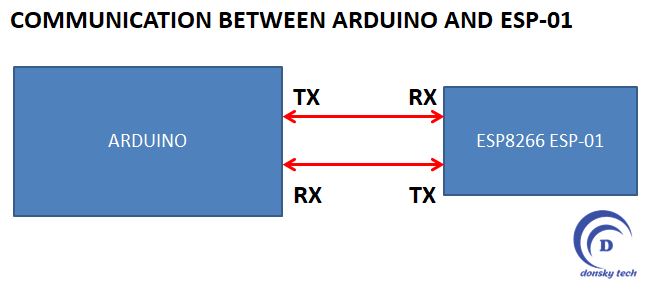
Take note from the diagram above that we will need to program both the Arduino Uno board and the ESP8266 ESP-01 separately. To emphasize, the Arduino Uno board is running a different program than the ESP8266 ESP-01 and they just communicate thru the serial pins.
The ESP8266 ESP-01 is the one communicating with your WiFi or the internet and whatever information it retrieved is passed back to the Arduino Uno board. For details on how to program your ESP8266 ESP-01 then please see below.
Related Content:
Program ESP8266 ESP-01 With Arduino
Wiring Diagram

Above is the wiring diagram for the communication between the Arduino and the ESP-01 thru the serial interface. The switch between the RST Pin of the ESP-01 to the GND is used if you want to restart the ESP-01.
Test JSON Endpoint
We are using the following free JSON endpoint (http://jsonplaceholder.typicode.com/) to retrieve sample data. And the target REST URL resource is the users (http://jsonplaceholder.typicode.com/users)
I used this here since there is no need for us to sign up and get API Key just like how we get weather data in the ThingSpeak server.
The following is the sample JSON response from the server.
{
  "id": 1,
  "name": "Leanne Graham",
  "username": "Bret",
  "email": "Sincere@april.biz",
  "address": {
    "street": "Kulas Light",
    "suite": "Apt. 556",
    "city": "Gwenborough",
    "zipcode": "92998-3874",
    "geo": {
      "lat": "-37.3159",
      "lng": "81.1496"
    }
  },
  "phone": "1-770-736-8031 x56442",
  "website": "hildegard.org",
  "company": {
    "name": "Romaguera-Crona",
    "catchPhrase": "Multi-layered client-server neural-net",
    "bs": "harness real-time e-markets"
  }
}
Code
The code for the ESP-01 is shown below:
This is available on my GitHub project site which you can access from here.
#include <ESP8266WiFi.h>
#include <ESP8266HTTPClient.h>
#include <ArduinoJson.h>

const char* ssid     = "<INSERT WIFI SSID>";
const char* password = "<INSERT YOUR PASSWORD HERE>";

const char* host = "jsonplaceholder.typicode.com";

void setup() {
  Serial.begin(9600);
  delay(10);

  // We start by connecting to a WiFi network
  Serial.println();
  Serial.println();
  Serial.print("Connecting to ");
  Serial.println(ssid);
  WiFi.mode(WIFI_STA);
  WiFi.begin(ssid, password);

  while (WiFi.status() != WL_CONNECTED) {
    delay(500);
    Serial.print(".");
  }

  Serial.println("");
  Serial.println("WiFi connected");
  Serial.println("IP address: ");
  Serial.println(WiFi.localIP());
}

int value = 0;

void loop() {
  ++value;
  // wait for WiFi connection
  if ((WiFi.status() == WL_CONNECTED)) {

    WiFiClient client;

    HTTPClient http;

    //Set the target url
    String url = "http://jsonplaceholder.typicode.com/users/";
    url+=value;

    if (http.begin(client, url)) {  // HTTP

      // start connection and send HTTP header
      int httpCode = http.GET();

      // httpCode will be negative on error
      if (httpCode > 0) {
        // HTTP header has been send and Server response header has been handled

        if (httpCode == HTTP_CODE_OK || httpCode == HTTP_CODE_MOVED_PERMANENTLY) {
          String payload = http.getString();
          sendDataBackToArduino(payload);

        }
      } else {
        Serial.printf("[HTTP] GET... failed, error: %s\n", http.errorToString(httpCode).c_str());
      }

      http.end();
    } else {
      Serial.printf("[HTTP} Unable to connect\n");
    }
  }

  //max number in the test json is 10, so we reset it back to 0 again to start over
  if(value == 10)
    value = 0;

  delay(10000);
}

void sendDataBackToArduino(String payload){
  const size_t capacity = JSON_OBJECT_SIZE(2) + JSON_OBJECT_SIZE(3) + JSON_OBJECT_SIZE(5) + JSON_OBJECT_SIZE(8) + 360;
  DynamicJsonDocument doc(capacity);
    // Parse JSON object
  DeserializationError error = deserializeJson(doc, payload);
  if (error) {
    Serial.print(F("deserializeJson() failed: "));
    Serial.println(error.c_str());
    return;
  }
  serializeJson(doc, Serial);
}- Line 5-6: Change this to your Wifi SSID and Password
- Lines 10-31: Code to connect thru our Wifi
- Lines 48-70: Connect to our JSON endpoint and retrieve the following details
- Lines 79-90: Handles the JSON response from the server and writes back the response to the Serial Interface.
We used the following ArduinoJson library to parse the JSON Response.
To load the program to the ESP-01 then you should set it to boot mode. If you need more information on how this is done then read how to load program esp-01 with Arduino.
The following is the code for the Arduino.
This is available in my GitHub account which you can access from here.
#include <Wire.h>
#include <LiquidCrystal_I2C.h>
#include <ArduinoJson.h>
#include <SoftwareSerial.h>

SoftwareSerial mySerial(2, 3); // RX, TX

LiquidCrystal_I2C lcd(0x27, 16, 2);

void setup() {
  Serial.begin(115200);
  mySerial.begin(9600);
  Serial.println("<Arduino is ready>");

  lcd.init();
  lcd.backlight();
}

void loop() {
  if (mySerial.available()) {
    parseAndDisplay();
  }
}

void parseAndDisplay() {
  const size_t capacity = JSON_OBJECT_SIZE(2) + JSON_OBJECT_SIZE(3) + JSON_OBJECT_SIZE(5) + JSON_OBJECT_SIZE(8) + 467;
  DynamicJsonDocument doc(capacity);
  DeserializationError error = deserializeJson(doc, mySerial);
  if (error) {
    Serial.print(F("deserializeJson() failed: "));
    Serial.println(error.c_str());
    return;
  }
  int id = doc["id"]; // 1
  const char * name = doc["name"]; // "Leanne Graham"
  const char * username = doc["username"]; // "Bret"
  const char * email = doc["email"]; // "Sincere@april.biz"

  JsonObject company = doc["company"];
  const char * company_name = company["name"]; // "Romaguera-Crona"
  const char * company_catchPhrase = company["catchPhrase"]; // "Multi-layered client-server neural-net"
  const char * company_bs = company["bs"]; // "harness real-time e-markets"

  Serial.print("ID :: ");
  Serial.println(id);
  Serial.print("Name :: ");
  Serial.println(name);
  Serial.print("Company Name :: ");
  Serial.println(company_name);

  printToLCDScreen(id, name);
}

void printToLCDScreen(const int id,
  const char * name) {
  lcd.setCursor(0, 0);
  lcd.print("Name:");
  lcd.setCursor(0, 1);
  lcd.print(name);
}- Lines 1-4: Declares the Library we are going to use to power the LCD and the JSON parser Library
- Line 6: We use a SoftwareSerial TX and RX pin to interface with the ESP-01
- Lines 10-17: Initialize the LCD Library.
- Lines 19-23: Waits for data coming from the serial interface
- Lines 25-52: Parses the data coming from the Serial Interface
- lines 54-60: Display it on the LCD Screen
Additional Notes:
The Baud rate should be set to 9600 or lower for the serial communication between the two MCU. If you happen to see any garbled messages then set it to lower like 4800.
Wrap up
We were able to connect our Arduino Uno board to our WiFi and retrieve information from the internet using the ESP8266 ESP-01 module. You are now ready to create your own Internet of Things (IoT) using your Arduino Uno board.
That’s it! Happy Exploring!
Leave a Reply