Introduction
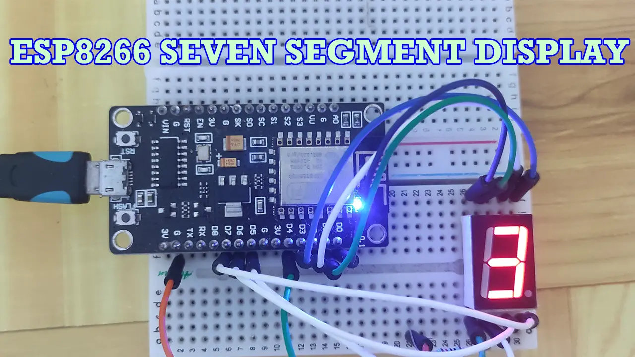
Do you want to know how to control those colored seven-segment displays using your NodeMCU ESP8266 and the Arduino framework then follow along with this short post. Those colorful seven-segment displays are ideal for Internet of Things (IOT) projects that need to display the current count or current mode of your project. They can even be used as a countdown or count-up timer.
Prerequisite
The following are the components and materials needed to follow along with this post.
- ESP8266 (I used NodeMCU ESP8266)
- Seven Segment Display
- Breadboard
- Wiring
I used Visual Studio Code with the PlatformIO extension installed in developing this project. If you are in Windows and have not yet installed Visual Studio Code then you can check my post about how to Install Visual Studio Code or VSCode in Windows. If you are not familiar with PlatformIO then please read this PlatformIO Tutorial for Arduino Development where I detailed how to get started with development using the PlatformIO IDE extension
What is a seven-segment display?
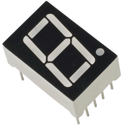
The seven-segment displays are electronic components that are capable of displaying numerical values which you can find in timer circuits most of the time. They are LEDs that are arranged in the “8” position and each LED represents a segment of the display. Please see the image below.
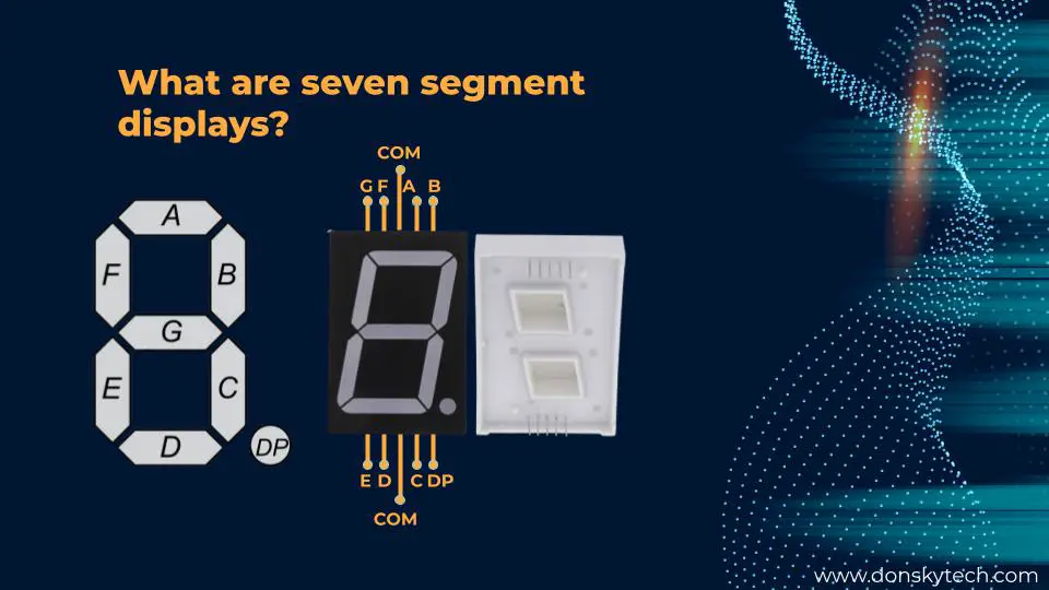
Each segment is represented by the label that you see above which starts from the letters A to G. The ‘DP” or Decimal Point is another segment that becomes useful if you are going to display multiple counters.
Each segment is then connected to the exterior pins of the seven-segment display. The arrangement is shown above. For example, if you want to display the numerical number “1” then lighting up the ‘B’ and ‘C’ segments will do this for you.
The LEDs that comprise the seven-segment display are arranged such that all the Anode or the Cathode terminals of each LED are grouped together and brought out as the COM or Common Pin. This makes the seven-segment display type either a Common-Anode or Common-Cathode type of display.
How do you know if your seven segments are common anode or common-cathode?
I usually connect a resistor in one of the common pins and connect it to the ground any of the other segment (A to G) ends is connected to the VCC pin. If it lights up then it is a common cathode otherwise it is a common-anode.
How to light up the segment?
If your seven-segment display type is common-cathode then applying a Logic High will light up the LED segments. On the other hand, if it is a common anode then applying a Logic Low will light up the LED segments.
Wiring/Schematic
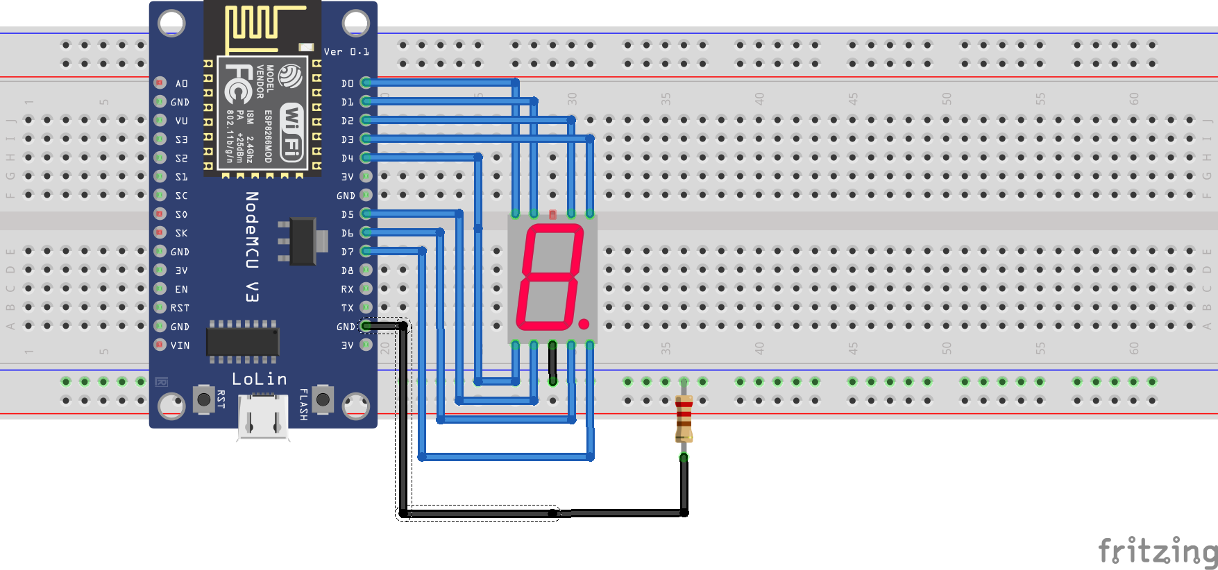
The following is the wiring and schematic diagram of how we are going to control our seven-segment display using our NodeMCU ESP8266 and the Arduino framework.
| ESP8266 | SEVEN SEGMENT |
|---|---|
| D0 | ‘g’ PIN |
| D1 | ‘f’ PIN |
| D2 | ‘a’ PIN |
| D3 | ‘b’ PIN |
| D4 | ‘e’ PIN |
| D5 | ‘d’ PIN |
| D6 | ‘c’ PIN |
| D7 | ‘point’ pin |
Just add a 220-ohm resistor in the common pin of the seven-segment displays as a current-limiting resistor to protect our component.
Code
The code for this project is in my GitHub repository which you can from here. You can either download or clone the project using Git and then open the folder in Visual Studio Code.
The complete code for this project is shown below and let us try to walk you through each line of the code.
#include <Arduino.h>

enum COMMON_TYPE
{
  COMMON_ANODE = 1,
  COMMON_CATHODE = 0
};
byte SEVEN_SEMENT_TYPE = COMMON_CATHODE;

const int PIN_COUNT = 8;

const byte A_PIN = D2;
const byte B_PIN = D3;
const byte C_PIN = D6;
const byte D_PIN = D5;
const byte E_PIN = D4;
const byte F_PIN = D1;
const byte G_PIN = D0;
const byte P_PIN = D7;

int segmentPins[]{A_PIN, B_PIN, C_PIN, D_PIN, E_PIN, F_PIN, G_PIN, P_PIN};

// count from 0-9
const byte DISPLAY_COUNT = 10;
const byte SEGMENT_COUNT = 8;
const byte COL_COUNT = 8;
int seven_segment[DISPLAY_COUNT][COL_COUNT]{
    {1, 1, 1, 1, 1, 1, 0, 0}, // Display 0
    {0, 1, 1, 0, 0, 0, 0, 0}, // Display 1
    {1, 1, 0, 1, 1, 0, 1, 0}, // Display 2
    {1, 1, 1, 1, 0, 0, 1, 0}, // Display 3
    {0, 1, 1, 0, 0, 1, 1, 0}, // Display 4
    {1, 0, 1, 1, 0, 1, 1, 0}, // Display 5
    {1, 0, 1, 1, 1, 1, 1, 0}, // Display 6
    {1, 1, 1, 0, 0, 0, 0, 0}, // Display 7
    {1, 1, 1, 1, 1, 1, 1, 0}, // Display 8
    {1, 1, 1, 1, 0, 1, 1, 0}  // Display 9
};

void setup()
{
  // Initialize the serial monitor baud rate
  Serial.begin(115200);

  // set all pins to output
  for (size_t i = 0; i < PIN_COUNT; i++)
  {
    pinMode(segmentPins[i], OUTPUT);
  }
}

void loop()
{
  // put your main code here, to run repeatedly:
  for (size_t iCtr = 0; iCtr < DISPLAY_COUNT; iCtr++)
  {
    for (size_t i = 0; i < COL_COUNT; i++)
    {
      digitalWrite(segmentPins[i], seven_segment[iCtr][i]);
    }
    delay(1000);
  }
}
#include <Arduino.h>Since we are using the Arduino framework the header file is included by default.
enum COMMON_TYPE
{
  COMMON_ANODE = 1,
  COMMON_CATHODE = 0
};
byte SEVEN_SEMENT_TYPE = COMMON_CATHODE;
We define what type of seven-segment display we have which could either be a common anode or cathode. It is important to properly set the variable byte SEVEN_SEMENT_TYPE = COMMON_CATHODE; to what component you have.
const int PIN_COUNT = 8;

const byte A_PIN = D2;
const byte B_PIN = D3;
const byte C_PIN = D6;
const byte D_PIN = D5;
const byte E_PIN = D4;
const byte F_PIN = D1;
const byte G_PIN = D0;
const byte P_PIN = D7;

int segmentPins[]{A_PIN, B_PIN, C_PIN, D_PIN, E_PIN, F_PIN, G_PIN, P_PIN};
We define the pin assignments from here which map to the GPIO pins of the NodeMCU ESP8266. Each pin is connected to the output pins of the seven-segment display. We define an array int segmentPins[]{A_PIN, B_PIN, C_PIN, D_PIN, E_PIN, F_PIN, G_PIN, P_PIN}; which we will use later in the code.
// count from 0-9
const byte DISPLAY_COUNT = 10;
const byte SEGMENT_COUNT = 8;
const byte COL_COUNT = 8;
int seven_segment[DISPLAY_COUNT][COL_COUNT]{
    {1, 1, 1, 1, 1, 1, 0, 0}, // Display 0
    {0, 1, 1, 0, 0, 0, 0, 0}, // Display 1
    {1, 1, 0, 1, 1, 0, 1, 0}, // Display 2
    {1, 1, 1, 1, 0, 0, 1, 0}, // Display 3
    {0, 1, 1, 0, 0, 1, 1, 0}, // Display 4
    {1, 0, 1, 1, 0, 1, 1, 0}, // Display 5
    {1, 0, 1, 1, 1, 1, 1, 0}, // Display 6
    {1, 1, 1, 0, 0, 0, 0, 0}, // Display 7
    {1, 1, 1, 1, 1, 1, 1, 0}, // Display 8
    {1, 1, 1, 1, 0, 1, 1, 0}  // Display 9
};
We define a two-dimensional array that defines which segment is to be lit up or not. Each 1 and 0 corresponds to the ‘a’, ‘b’, ‘c’ , ‘d’ , ‘e’ , ‘f’ , ‘g,’ and ‘.’ segments of our seven-segment display. So rather than setting the output per each segment using digitalWrite, it would be much better to use this array.
void setup()
{
  // Initialize the serial monitor baud rate
  Serial.begin(115200);

  // set all pins to output
  for (size_t i = 0; i < PIN_COUNT; i++)
  {
    pinMode(segmentPins[i], OUTPUT);
  }
}
Standard setup() function where we set the baud rate of our Serial Monitor and set all NodeMCU ESP8266 pins to output mode.
void loop()
{
  // put your main code here, to run repeatedly:
  for (size_t iCtr = 0; iCtr < DISPLAY_COUNT; iCtr++)
  {
    for (size_t i = 0; i < COL_COUNT; i++)
    {
      digitalWrite(segmentPins[i], seven_segment[iCtr][i]);
    }
    delay(1000);
  }
}
In this loop function, we iterate all of our seven_segment multi-dimensional arrays wherein we are counting from 0 to 9. For each row in our multi-dimensional arrays, we lit up each segment corresponding to the current count. After displaying, we sleep for 1 sec.
That’s all there is for the code! Easy, isn’t it? Yay!
Wrap Up
In this post, we have gone through how to control our seven-segment display using our NodeMCU ESP8266 and the Arduino framework. I hope you learned something from this short post. We will use this project later to discuss other topics and projects.
Stay tuned! Happy Exploring!
Support Me!
I love sharing what I know and hopefully, I was able to help you. Writing helpful content takes so much time and research. If you think you like my work and I have managed to help you then please consider supporting my channel. I would be very grateful and would boost my confidence that what I am doing is making a big change in the world. (No Pun Intended!) 😉
Become a Patron!
Leave a Reply