Introduction
In this post, we are going to explore how to control your servo motor using your Raspberry Pi and Python code. We will explore some issue(s) that you might encounter while programming this component and how to solve it.
If your Internet of Things (IoT) project requires precision control like controlling the movement of a robot or a needle movement of a 3D printer or a simple movement mechanism like opening or closing a door lock then a servo motor is what you need together with your raspberry pi.
If you like video presentations then please see this project in action on my YouTube channel.
Prerequisites
The following components/tools are needed in order to follow along with this post.
- Raspberry Pi ( I used Raspberry Pi Zero W)
- Servo Motor (either SG90 or MG90)
- Breadboard
- Connecting wires
My Raspberry Pi Zero is using the latest Raspberry Pi OS and if you need help in setting up a new OS in your Pi then you can follow my earlier post. This is a headless setup so no external monitor or keyboard is needed.
What is a Servo motor?
Servo motors are an excellent choice if you want precision control of movement for your project’s mechanical parts. The range of motion for this type of special motor is limited to 180 degrees.
A servo motor or (servomotor) is a type of motor that combines a rotary encoder and a potentiometer to create what we call a servomechanism. If your Internet of Things (IoT) project requires precise motion control then a servo motor can help you in this.
If you take a look inside the construction of a servo motor then you would see that it has a DC or AC motor, some gear assembly connected to an output shaft, and a controlling feedback circuit. This is more of a closed-loop system
For a much more detailed explanation of how servo motor works then please see this wikipedia link.
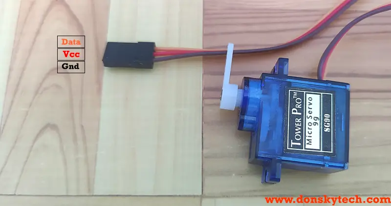
Servo Pinout
The servo usually comes in 3 pins with the Vcc, GND, and Data or PWM signal pin. The Data or PWM signal pins come in orange sometimes and it is connected to the GPIO of your microcontroller. In the case of Raspberry Pi, we can either connect it with any GPIO pins or much better pins that have hardware PWM setup by default.
How to control Servo?
To control the position of our Servo Motor we need to send a series of pulses to its data or signal pin. In the case of the Raspberry Pi, we will send a PWM signal with a different duty cycle.
Looking at the datasheet of an SG90 servo motor from here, the pulse cycle is 20ms (equivalent to 50Hz) and to control the position we need to set the following duty cycle. Take note of the following diagram below as to how we can control its direction.

We need to take note of the following mathematical items before we proceed.
- Period = 1/Frequency = 1/50Hz = 20ms
- To set the servo motor shaft to the full left position we need to send a pulse width of 1ms.
Duty Cycle = Pulse Width (in secs) /Period (in secs) = .001(secs)/.02(secs) = 0.05 or 5%- To set the servo motor shaft to the middle position then we need to send a pulse width of 1.5ms.
Duty Cycle = Pulse Width (in secs) /Period (in secs) = .0015(secs)/.02(secs) = 0.075 or 7.5%- To set the servo motor shaft to the full right position we need to send a pulse width of 2ms.
Duty Cycle = Pulse Width (in secs) /Period (in secs) = .002(secs)/.02(secs) = 0.1 or 10%To summarize, we need to set our PWM signal duty cycle for our Raspberry Pi GPIO pins between 5% to 10% to make it move fully from left to right. You will see this later when we are coding and why knowledge of the duty cycle is needed.
NOTE: This is the ideal case for a servo motor however you would find out that sometimes it does not move the full 180 degrees by using this setup. Please see the issue section below.
Wiring/Schematic
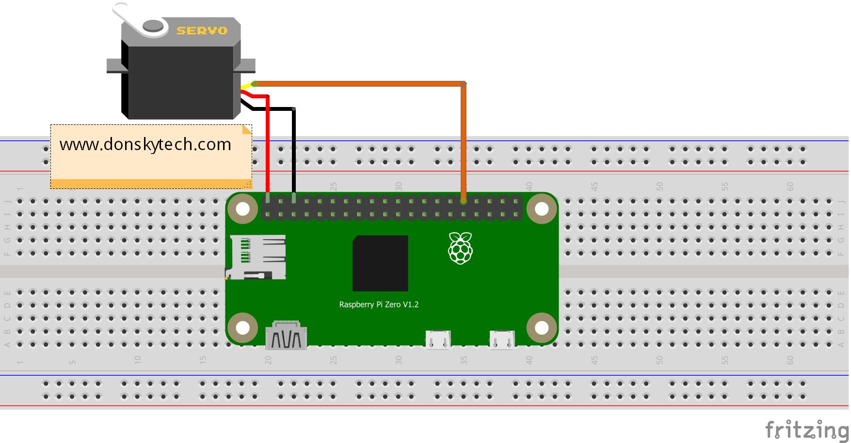
| Servo | Raspberry Pi |
|---|---|
| GND | GND |
| Vin | Vin |
| Data or PWM Signal | GPIO12 |
Note: It is much better to supply a different power source with constant current to the servo motor as it might draw more current. Just remember to connect the ground of the raspberry pi and the power source.
Code
Using the information about the duty cycle above we can create the following code to drive our servo motor using our Raspberry Pi. This is available also in my github account so either you download or clone my repository from there.
We will be coding in two Raspberry Pi packages using the RPi.GPIO and the gpiozero. Both of these packages are now installed by default in the latest Raspberry Pi OS.
RPi.GPIO
# Title:  SG90 Servo Driver Code - RPi.GPIO
# Author: donskytech

import RPi.GPIO as GPIO
import time

# setup RPi
GPIO.setwarnings(False)
servo_pin = 12
GPIO.setmode(GPIO.BCM)
GPIO.setup(servo_pin,GPIO.OUT)

# 50 Hz or 20 ms PWM period
pwm = GPIO.PWM(servo_pin,50)

print("Starting at zero...")
pwm.start(5)

try:
    while True:
        print("Setting to zero...")
        pwm.ChangeDutyCycle(5)
        time.sleep(1)

        print("Setting to 180...")
        pwm.ChangeDutyCycle(10)
        time.sleep(1)

        print("Setting to 90...")
        pwm.ChangeDutyCycle(7.5)
        time.sleep(1)
except KeyboardInterrupt:
    pwm.stop()
    GPIO.cleanup()
    print("Program stopped")
- Line 4-5: We import the necessary packages
- Line 8-11: configure the Rpi.GPIO setup including the servo pins
- Line 14-17: Start our PWM pin passing a 50Hz and the servo pin
- Line 20: We have an infinite loop that will cycle through our servo movement
- Line 21-31: We change the duty cycle from 5% to 10% to move the servo horn from 0(zero) to 180 degree
- Line 32-35: We clean in case we terminate our Python script.
gpiozero
Another popular library is the gpiozero which provides classes that abstract much of the GPIO complexity. They have a servo class that represents this component and we can just call methods from that class. Please see the sample code below.
# Title:  SG90 Servo Driver Code  - GPIOZero
# Author: donskytech

from gpiozero import  Servo
from time import sleep

servo = Servo(12)

try:
    while True:
        print("Setting to min...")
        servo.min()
        sleep(1)

        print("Setting to mid...")
        servo.mid()
        sleep(1)

        print("Setting to max...")
        servo.max()
        sleep(1)
except KeyboardInterrupt:
print("Exiting program")- Line 4-5: import the gpiozero packages
- Line 7: Initialize a servo class
- Line 10: We create an infinite loop to run our sequence
- Line 11-2: We move the servo from zero to 90 to 180 degrees by calling the min(), mid(), and max() method of the servo class.
Issues:
Why is my servo motor not moving full 180o (degrees)?
The image above shows that the movement of your servo is not the full 180 degrees even though we follow the recommended duty cycle. Different servos have different peculiarities so it is much better to test it while you are coding.
To fix the issue, let us adjust the duty cycle in our Python code. In my SG90 Servo, the following code works. As you can see, the major difference is the duty cycle setup.
| Rotation | Recommended | Modified |
|---|---|---|
| 0 degree | 5 | 3 |
| 180 degree | 10 | 13 |
| 90 degree | 7.5 | 8 |
# Title:  SG90 Servo Driver Code - RPi.GPIO
# Author: donskytech

import RPi.GPIO as GPIO
import time


# setup RPi
GPIO.setwarnings(False)
servo_pin = 12
GPIO.setmode(GPIO.BCM)
GPIO.setup(servo_pin,GPIO.OUT)

# 50 Hz or 20 ms PWM period
pwm = GPIO.PWM(servo_pin,50)

print("Starting at zero...")
pwm.start(3)

try:
    while True:
        print("Setting to zero...")
        pwm.ChangeDutyCycle(3) #  Duty Cycle Adjusted
        time.sleep(1)

        print("Setting to 180...")
        pwm.ChangeDutyCycle(13) #  Duty Cycle Adjusted
        time.sleep(1)

        print("Setting to 90...")
        pwm.ChangeDutyCycle(8) #  Duty Cycle Adjusted
        time.sleep(1)
except KeyboardInterrupt:
    pwm.stop()
    GPIO.cleanup()
    print("Program stopped")
If you are using gpiozero in driving your servo motor then take a look at the following modified code. Can you guess how did I arrive with the new setup for min_pulse_width and max_pulse_width?
# Title:  SG90 Servo Driver Code - GPIOZero
# Author: donskytech

from gpiozero import Servo
from time import sleep

servo = Servo(12, min_pulse_width=0.0006, max_pulse_width=0.0026)

try:
    while True:
        print("Setting to min...")
        servo.min()
        sleep(1)

        print("Setting to mid...")
        servo.mid()
        sleep(1)

        print("Setting to max...")
        servo.max()
        sleep(1)
except KeyboardInterrupt:
	print("Exiting program")
From the documentation of the gpiozero for servo, we can deduce that the default min and max pulse width is between 1ms to 2ms which is equivalent to a 5% and 10% duty cycle. However, from our testing and the table above, it looks like the best way to control it is from 3% to 13%.
So using these new values we can substitute them now to the default value of the servo class of the gpiozero when we initialize servo = Servo(12, min_pulse_width=0.0006, max_pulse_width=0.0026)
#### For a 3% min duty cycle
Duty Cycle = Pulse Width/Period
.03 = Pulse Width/0.02
Pulse Width = 0.03 * 0.02
Pulse Width = 0.0006

#### For a 13% min duty cycle
Duty Cycle = Pulse Width/Period
.13 = Pulse Width/0.02
Pulse Width = 0.13 * 0.02
Pulse Width = 0.0026
How about other servos like MG90 not in full 180-degree movement?
Then you need to figure it out yourselves also. Mine was like this code.
# Title:  SG90 Servo Driver Code - RPi.GPIO
# Author: donskytech

import RPi.GPIO as GPIO
import time


# setup RPi
GPIO.setwarnings(False)
servo_pin = 12
GPIO.setmode(GPIO.BCM)
GPIO.setup(servo_pin,GPIO.OUT)

# 50 Hz or 20 ms PWM period
pwm = GPIO.PWM(servo_pin,50)

print("Starting at zero...")
pwm.start(2)

try:
    while True:
        print("Setting to zero...")
        pwm.ChangeDutyCycle(2)
        time.sleep(1)

        print("Setting to 180...")
        pwm.ChangeDutyCycle(11)
        time.sleep(1)

        print("Setting to 90...")
        pwm.ChangeDutyCycle(6.5)
        time.sleep(1)
except KeyboardInterrupt:
    pwm.stop()
    GPIO.cleanup()
    print("Program stopped")
The Servo motor is jittering
Usually, this might be caused by not enough current flowing to the servo motor. Power up the servo with an external supply and connect the common ground with your Raspberry Pi.
Wrap Up
We have explored how to program and connect your servo motor with your Raspberry Pi in this post. I have explained the logic behind the programming and stated several issues that you might encounter.
That’s it! Happy Exploring!
Support Me!
I love sharing what I know and hopefully, I was able to help you. Writing helpful content takes so much time and research. If you think you like my work and I have managed to help you then please consider supporting my channel. I would be very grateful and would boost my confidence that what I am doing is making a big change in the world. (No Pun Intended!) 😉
Become a Patron!
Leave a Reply