Introduction
This post will discuss how you can setup your Keypad membrane with your raspberry pi. Keypad comes in different dimensions and they are ideal for applications that requires password authentication like security systems.
If you prefer watching videos or want to see it in action then please take a look below.
Prerequisites
I have installed the latest Raspberry Pi OS in my Raspberry Pi W Zero. If you haven’t done so then please follow along with this post where I setup my unit in headless mode without any external keyboard or monitors attached.
The following components or materials are needed to follow along with this post.
- Raspberry Pi ( I used Raspberry Pi Zero W)
- 4X4 Keypad Membranes
- Breadboard
- Connecting Wires
Components
Keypad Membrane
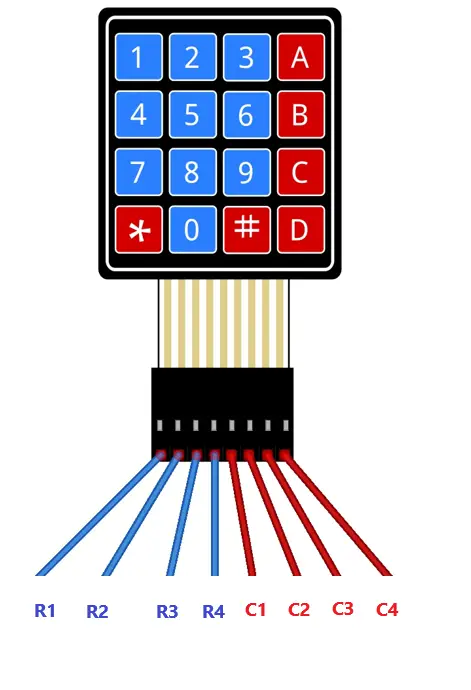
Membrane keypads comes in different dimensions such as a 4×3 or 4×4 (e.g number of rows X number of columns). The pinouts above shows a 4×4 keypad membrane with the first 4 pins allotted to its rows and the next 4 to the columns. They are arranged in a matrix like manner to limit the number of pins and uses a membrane switch under the hood.
You don’t need external power to connect to this component as any microcontroller GPIO could sufficiently drive this component.
How do we read the Keypad input with our Raspberry pi?
The image above will show the logic on how we are going to read our keypad keypress. As I have mentioned, the membrane switches are arranged in a matrix manner.
- The columns (C1, C2, C3, C4) are pulled up HIGH by default when no keypress is initiated.
- For each row (R1,R2,R3,R4), we send a pulse of LOW like connecting it to GND pin. We then check each switch in each column to verify if anything has been pulled low.
- In the case above, if the key “1” was pressed then the column (C1) is like being “shorted” to the ground causing a read value of “LOW”. Then it proceeds to the next column until the end.
- Then we pulse the next Row and check each columns until the end which is R4 in this case.
- After looping each row, we reset it back to High.
Kindly note of these things in the diagram.
- You can disregard the 10K ohm resistor symbol there as I just put it there to avoid shorting our GPIO directly to the ground source and act as a load.
- We can actually switch or invert the Column and Row values by pulling down the column to Low and then sending a Pulse of High in each row. Either way will work.
You will see this in action in the Code section of this post.
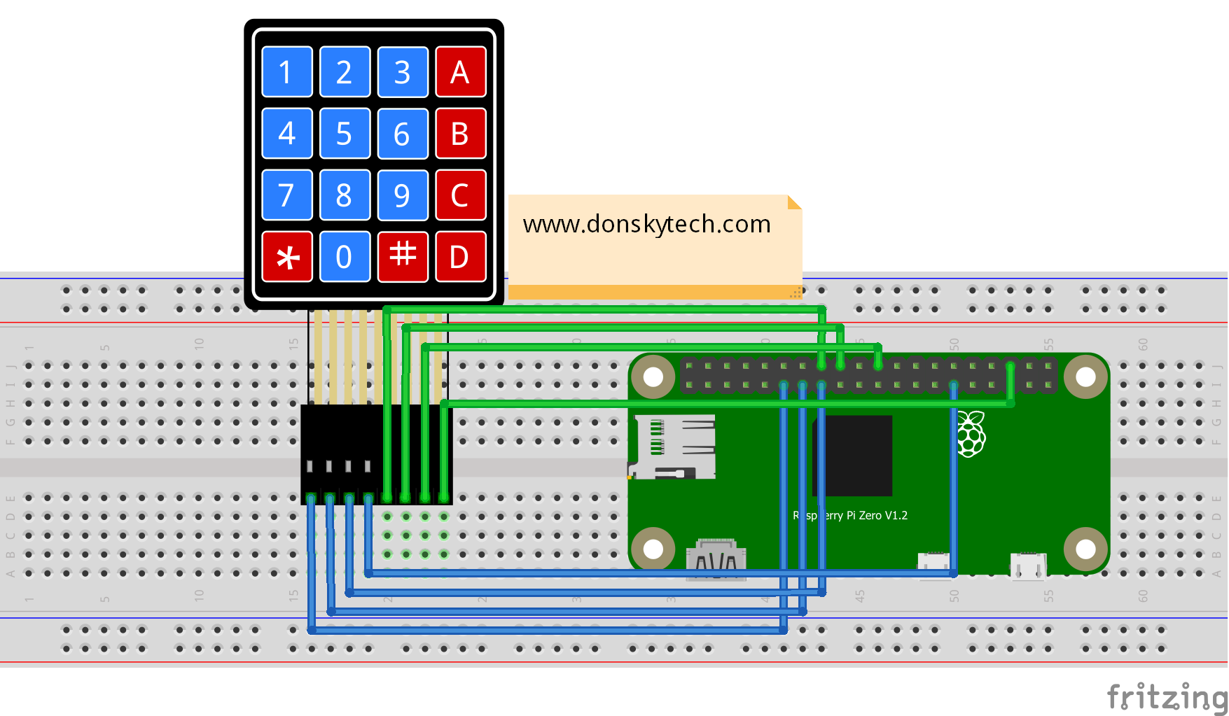
Wiring/Schematic – Keypad to Raspberry Pi
| Keypad | Raspberry Pi |
|---|---|
| R1 | GPIO17 |
| R2 | GPIO27 |
| R3 | GPIO22 |
| R4 | GPIO5 |
| C1 | GPIO23 |
| C2 | GPIO24 |
| C3 | GPIO25 |
| C4 | GPIO16 |
Code
We could use two approach when working with keypad wherein we could use Polling or Interrupt in reading the keypress. I have detailed this in the following sub sections.
Using Polling
As mentioned in the earlier section about how to read our keypad input using your raspberry pi, the code below will explain it in detail.
import RPi.GPIO as GPIO
import time

# Set the Row Pins
ROW_1 = 17
ROW_2 = 27
ROW_3 = 22
ROW_4 = 5

# Set the Column Pins
COL_1 = 23
COL_2 = 24
COL_3 = 25
COL_4 = 16

GPIO.setwarnings(False)
# BCM numbering
GPIO.setmode(GPIO.BCM)

# Set Row pins as output
GPIO.setup(ROW_1, GPIO.OUT)
GPIO.setup(ROW_2, GPIO.OUT)
GPIO.setup(ROW_3, GPIO.OUT)
GPIO.setup(ROW_4, GPIO.OUT)

# Set column pins as input and Pulled up high by default
GPIO.setup(COL_1, GPIO.IN, pull_up_down=GPIO.PUD_UP)
GPIO.setup(COL_2, GPIO.IN, pull_up_down=GPIO.PUD_UP)
GPIO.setup(COL_3, GPIO.IN, pull_up_down=GPIO.PUD_UP)
GPIO.setup(COL_4, GPIO.IN, pull_up_down=GPIO.PUD_UP)

# function to read each row and each column
def readRow(line, characters):
    GPIO.output(line, GPIO.LOW)
    if(GPIO.input(COL_1) == GPIO.LOW):
        print(characters[0])
    if(GPIO.input(COL_2) == GPIO.LOW):
        print(characters[1])
    if(GPIO.input(COL_3) == GPIO.LOW):
        print(characters[2])
    if(GPIO.input(COL_4) == GPIO.LOW):
        print(characters[3])
    GPIO.output(line, GPIO.HIGH)

# Endless loop by checking each row
try:
    while True:
        readRow(ROW_1, ["1","2","3","A"])
        readRow(ROW_2, ["4","5","6","B"])
        readRow(ROW_3, ["7","8","9","C"])
        readRow(ROW_4, ["*","0","#","D"])
        time.sleep(0.2) # adjust this per your own setup
except KeyboardInterrupt:
    print("\nKeypad Application Interrupted!")
GPIO.cleanup()- Line 1 – 2 : define the needed import modules
- Line 5 -14 : set the rows and column GPIO pins
- Line 16 -18 : rpi.gpio setup
- Line 5 -14 : set the rows and column GPIO pins
- Line 21 – 24 : set up row pins as output
- Line 27 – 30 : set column pins as input with pull up option
- Line 33 – 43 : readRow function will scan each column pin if any is set to low by pressing the keypad membrane switch
- Line 46 – 55 : polling each row and calling the readRow function
To run the script then enter the following command in your Raspberry Pi terminal.
sudo python test_keypad_polling.pyNote that the code above does not handle debouncing of switch or cases where you would like to restrict multiple entry of the same key.
Using interrupt
You will probably noticed in the code above that we are using a “while” loop to poll for each rows in our Keypad. This is fine for simple project but if your project is being interfaced with other system like a Graphical User Interface (GUI) then this might not work.
An alternative is to use an “interrupt” based library that we can used to setup an event handler to each switch of our keypad. The Raspberry Pi would then be notified or interrupted if the membrane switch was click or not.
The code below will explain this to you in detail. As you can see, we don’t have a polling while loop anymore in the code that scans each row. Press the “1” key in your keypad and you would be notified if the button was pressed and de-pressed.
import RPi.GPIO as GPIO
import time

def event_callback(pin):
    value = GPIO.input(pin)
    print(f"pin :: {pin}, value is {value}")

if __name__ == '__main__':
    button_pin = 23
    row_pin = 17

    GPIO.setmode(GPIO.BCM)
    GPIO.setwarnings(False)
    GPIO.setup(row_pin, GPIO.OUT)
    GPIO.setup(button_pin, GPIO.IN, pull_up_down = GPIO.PUD_UP)

    GPIO.output(row_pin, GPIO.LOW)

    # events can be GPIO.RISING, GPIO.FALLING, or GPIO.BOTH
    GPIO.add_event_detect(button_pin, GPIO.BOTH,
                          callback=event_callback,
                          bouncetime=300)

    try:
        time.sleep(1000)
    except KeyboardInterrupt:
        GPIO.cleanup()
To run this code then enter the following in your terminal. I noticed that the value goes to 0 when I click the switch and then to 1 when I release it.
pi@raspberrypi-zero-w:~/keypad_db $ sudo python test_edge_detection.py
#### Output
pin :: 23, value is 0
pin :: 23, value is 1
pin :: 23, value is 0
pin :: 23, value is 1
pin :: 23, value is 0
pin :: 23, value is 1
pin :: 23, value is 0
pin :: 23, value is 1
pin :: 23, value is 0
pin :: 23, value is 1
Using pad4pi interrupt package
With these understanding, I search for a library that has this functionality and I saw this library called pad4pi in the pypi repository and it looks promising. To install it in your Raspberry Pi then just execute the following command.
pip install pad4piAfterwhich, we wrote the following test script. Take a look at the code and the demo test scripts at the home page of this library.
#!/usr/bin/python

from pad4pi import rpi_gpio
import time

KEYPAD = [
    [1, 2, 3, "A"],
    [4, 5, 6, "B"],
    [7, 8, 9, "C"],
    ["*", 0, "#", "D"]
]

ROW_PINS = [17, 27, 22, 5] # BCM numbering
COL_PINS = [23, 24, 25, 16] # BCM numbering

def print_key(key):
    print(f"Received key from interrupt:: {key}")

try:
    factory = rpi_gpio.KeypadFactory()
    keypad = factory.create_keypad(keypad=KEYPAD,row_pins=ROW_PINS, col_pins=COL_PINS) # makes assumptions about keypad layout and GPIO pin numbers

    keypad.registerKeyPressHandler(print_key)

    print("Press buttons on your keypad. Ctrl+C to exit.")
    while True:
        time.sleep(1)
except KeyboardInterrupt:
    print("Goodbye")
finally:
keypad.cleanup()- Line 3-4: import necessary modules
- Line 6-14: define our keys and the rows and pins gpio
- Line 16-18: callback function that get’s called when the keypad button switch is pressed
- Line 19-31: pad4pi initialization script and registering callback handler
To run the code execute the following command
pi@raspberrypi-zero-w:~/keypad_db $ sudo python test_keypad_interrupt.py
Press buttons on your keypad. Ctrl+C to exit.
Received key from interrupt:: 1
Received key from interrupt:: *
Received key from interrupt:: 4
Received key from interrupt:: 5
Received key from interrupt:: 2
Received key from interrupt:: A
Received key from interrupt:: D
Wrap Up
We have described how the keypad works and how to drive it with our raspberry pi in this post. I have shown also ways on how to read the keypad input using two techniques.
That’s it! Happy Exploring!
Leave a Reply