Introduction
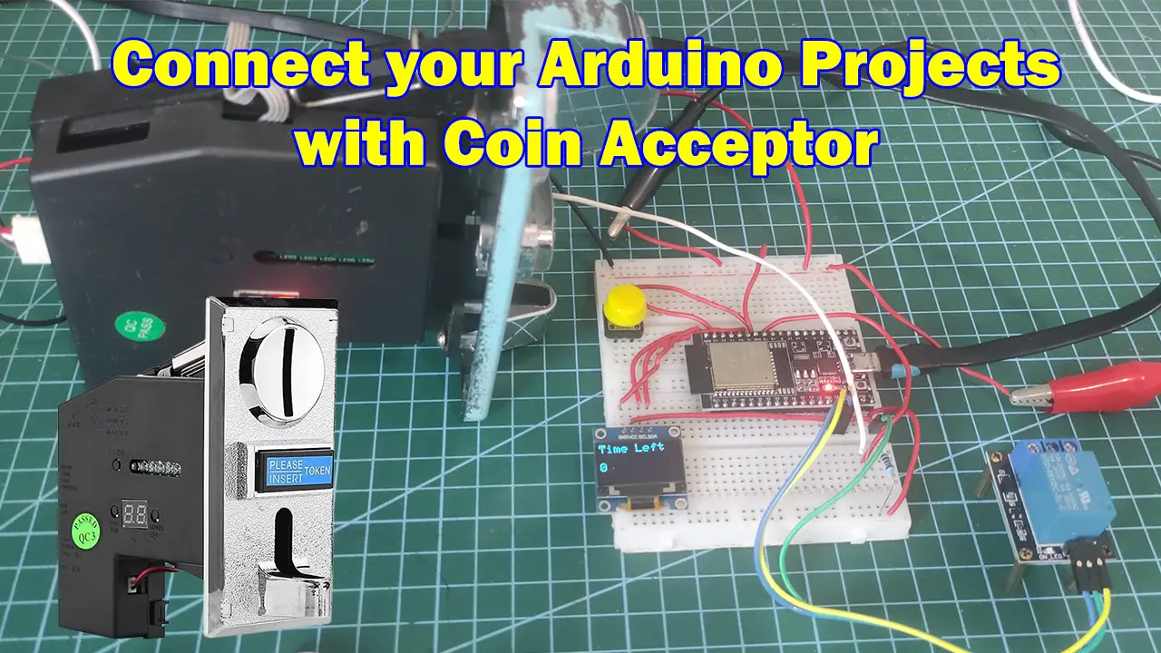
Would you like to physically earn money from your Arduino projects then add a universal coin acceptor in it and let the money flow? Kidding aside! This post will show you how you can interface your Arduino projects with a universal coin acceptor. I will be using an ESP32 microcontroller board running the Arduino framework and an OLED display to show messages to your users.
If you like to see this project in video format then please see the below video or watch it on my YouTube channel.
What is a Coin Acceptor?
Coin acceptor modules are widely used in different applications such as:
- Vending Machines
- Arcade Games
- Self-service stations such as massage chairs or mobile phone charging
They are easy to use and programmed to recognize different coin denominations and even identify fake coins. Using this module in your IoT projects would let you create or offer services that would allow you to earn for the services you render.
Coin Acceptor Pinout
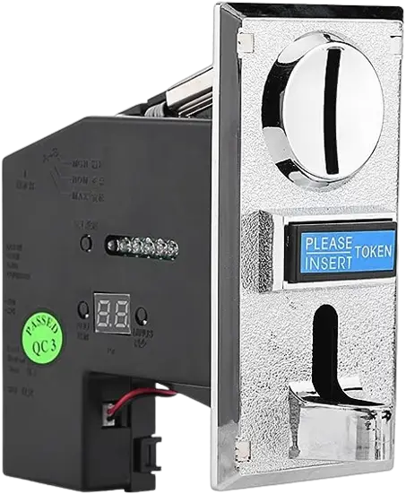
There are quite different models of coin acceptors created by different manufacturers. Some are even smart and has built-in coin counter and additional features. In my case, I am using the common CH926 model of the coin acceptor.
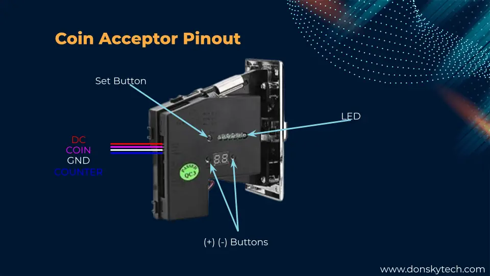
It has 4 control pins and several additional buttons that you can push to program it so that it can recognize different denominations. The image above will show you the common CH926 coin acceptor model pinout.
Note that most of the coin acceptor accepts a 12V DC voltage so you may need an external power supply to make them work.
How to program the Coin Acceptor?
You should program your coin acceptor to recognize the coins that it would accept. As each coin has a different denomination, the coin acceptor should properly notify you about the value of the coin that was inserted.
Different models of coin acceptors have different processes for programming them so you should refer to your manufacturer manual. But if you have the same model as mine (CH926) then you can refer to this manual.
How to connect your Arduino-based microcontroller with a universal coin acceptor?
After you have successfully programmed your coin acceptor you can start connecting it to your chosen Microcontroller. I have used an ESP32 development board as I would need its WiFi capability in a separate project later.
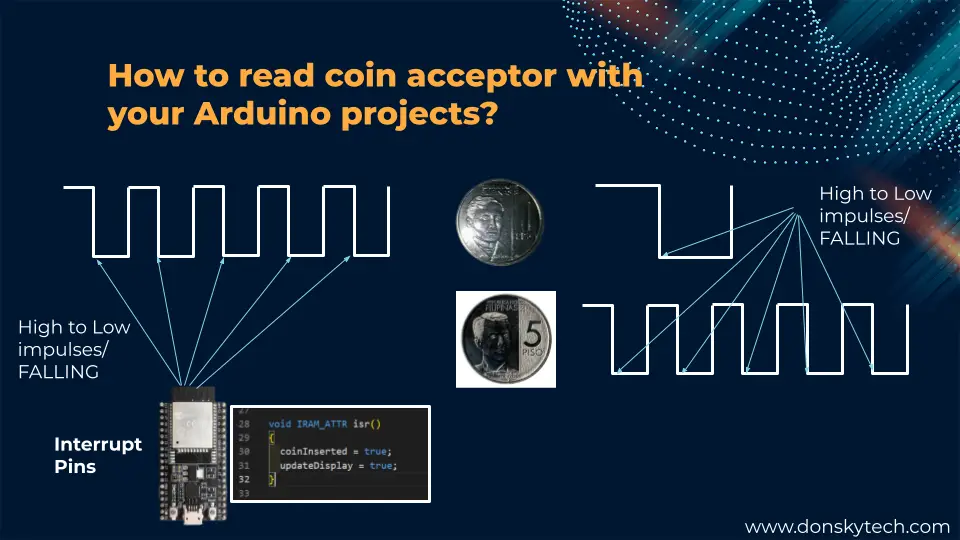
The universal coin acceptor would oftentimes output a short burst of signal that we can use to track the denomination of the coin that was inserted.
For example in the image above, a single peso (Philippine 1 Peso Coin) would output a single high-to-low transition or what they commonly call a FALLING edge. On the other hand, a 5 peso coin would result in five high-to-low transitions.
To detect these transitions we could take advantage of the interrupt pins on our Microcontroller and count the number. We need to write ISR (interrupt Service Routines) functions that would be notified when the Falling edge transition is detected on our interrupt pins. This is how easy it is to read the amount of coins that were inserted into our coin acceptor.
ESP32 with Coin Acceptor and OLED Display
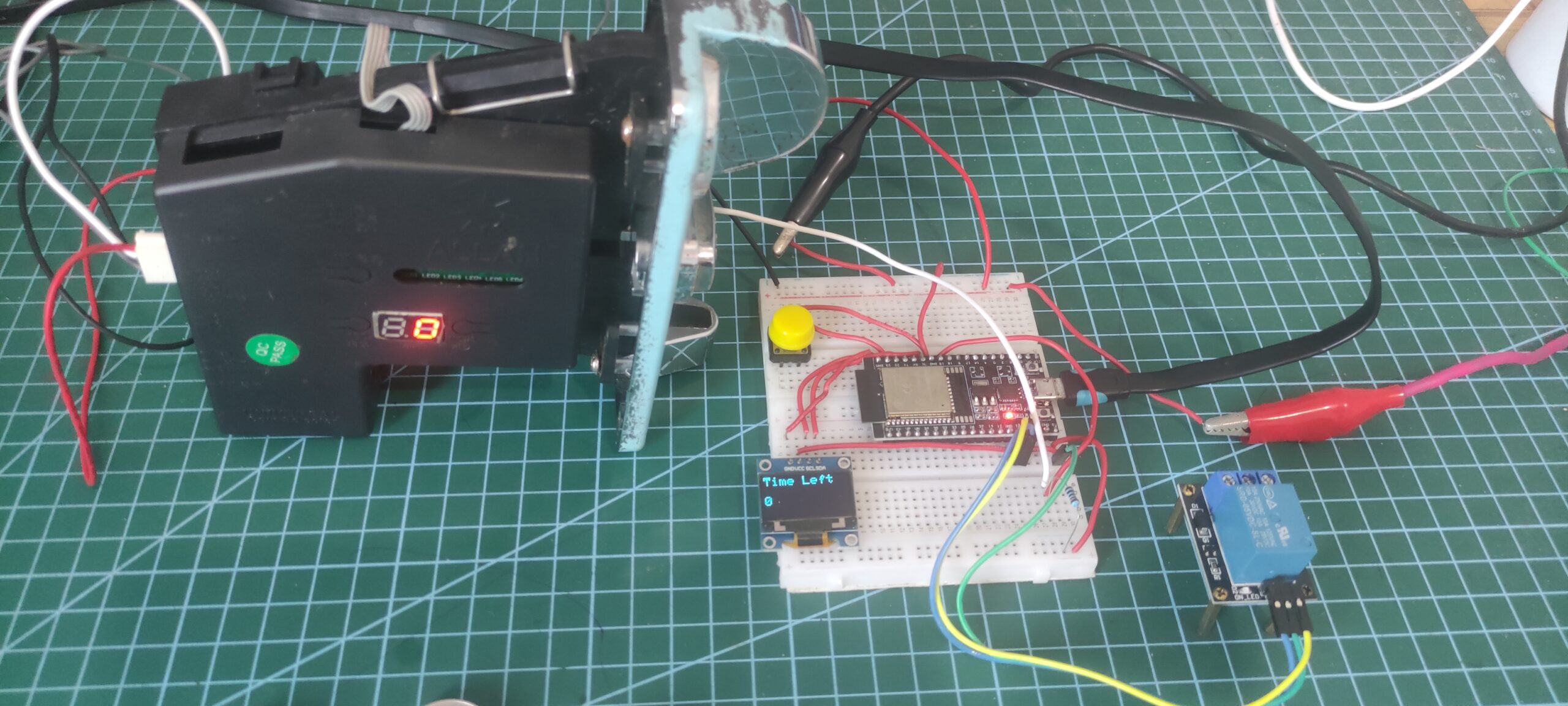
In this project of mine, I am creating a mobile solar charging station wherein the duration of the charging is set by the amount you inserted on your coin acceptor.
I have used an ESP32 board running the Arduino framework and an SSD1306 OLED display to show the time. The OLED would display the amount that was inserted and the remaining time
You can actually use a 4-digit tube LED like the TM1637 but I like the OLED display as I can put informational text aside from the countdown display.
If you have external circuitry that you want to drive then a relay could handle that for you.
Prerequisites
I am using Visual Studio Code with PlatformIO extensions in developing this project but you can use Arduino IDE just the same.
If you are not familiar with how to use PlatformIO then please see the below links that I have created just for that purpose.
Related Content:
PlatformIO Tutorial for Arduino Development
Install Visual Studio Code or VSCode in Windows
Parts/Components
The following are the components needed to follow along with this project
- Universal Coin Acceptor – Amazon | AliExpress
- ESP32 Microcontroller – Amazon | AliExpress
- SSD1306 OLED – Amazon | AliExpress
- Single Relay – Amazon | AliExpress
- Breadboard – Amazon | AliExpress
- Jumper Wires – Amazon | AliExpress
- External Bench Power Supply – Amazon | AliExpress
Take note of the Coin Acceptor model that you buy as it could be different from what I have used with this project. Talk to your store and ask for guidance on how to program your coin acceptor.
Disclosure: These are affiliate links and I will earn small commissions to support my site when you buy through these links.
Wiring/Schematics
The below image shows the wiring and the schematics that I have used for this project.
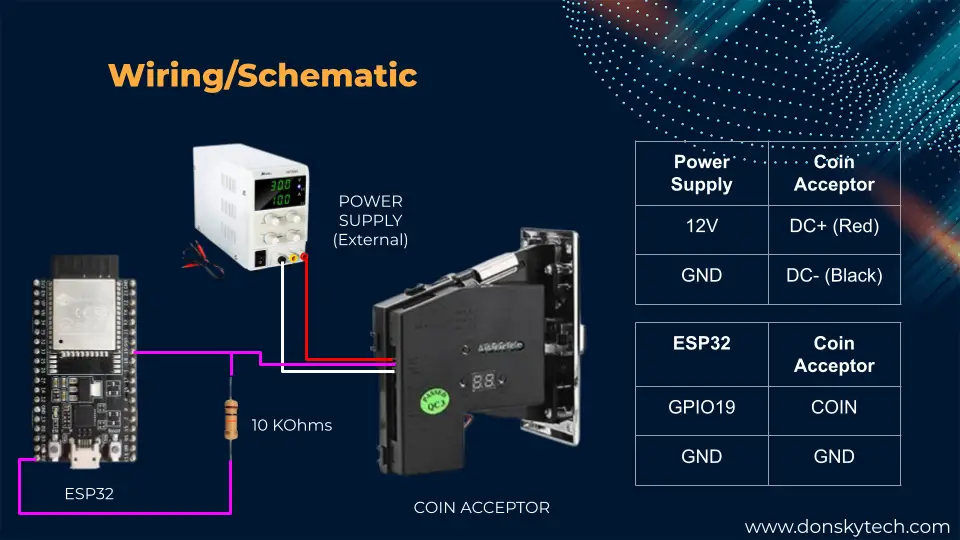
Make sure to add a 10K Ohms pull-up resistor to the COIN or signal line of the Coin Acceptor.
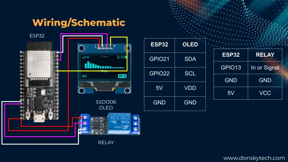
I am using an I2C OLED display here so I only needed 4 pins to connect with my ESP32. Your relay could be low-level or high-level triggered so you should adjust the code depending on the relay module that you have.
Code
The code for this project is available on my GitHub repository and you can either download it as a zip file or clone it using Git using the below command. Open the following project in Visual Studio Code using the PlatformIO extension.
git clone https://github.com/donskytech/platformio-projects.git
cd esp32-projects
 /esp32-coin-acceptor
code .
Libraries Used
We need two libraries so that we can drive our SSD1306 OLED display and a utility library that we can use to count the elapsed time. As you know, each coin denomination needs to map to a specific time duration.
They are included in the platform.ini file of this project. Note that if you are using Arduino IDE then you need to manually add the two libraries above.
[env:esp32dev]
platform = espressif32
board = esp32dev
framework = arduino
lib_ldf_mode = deep
lib_deps =
	adafruit/Adafruit SSD1306@^2.5.7
	pfeerick/elapsedMillis@^1.0.6
OLED Display
In order to simplify our main program it would be easier to create a separate class that would handle the logic that will display text on our SSD1306 display. This would help declutter our main program with unnecessary logic.
I have created two files for this which are the OLED_Displayer.h and the OLED_Displayer.cpp
#ifndef OLED_DISPLAYER
#define OLED_DISPLAYER
#include "Arduino.h"
#include <Wire.h>
#include <Adafruit_GFX.h>
#include <Adafruit_SSD1306.h>

class OLEDDisplayer
{
private:
    int width;
    int height;
    Adafruit_SSD1306 display;

public:
    OLEDDisplayer(int, int, Adafruit_SSD1306);
    void begin();
    void displayText(const char *text1, const char *text2 = "", uint8_t textSize = 1);
    void displayText(const char *text1, uint8_t amount, uint8_t textSize = 1);
    void clearOLEDDisplay();
};
#endif
This is our header file that declares a class called OLEDDisplayer. It has methods that we can use so that we can display text on our SSD1306 display. Notice also that in the constructor OLEDDisplayer(int, int, Adafruit_SSD1306); of this class it is expecting a parameter of type Adafruit_SSD1306 which we are going to supply later.
#include "OLED_Displayer.h"

OLEDDisplayer::OLEDDisplayer(int w, int h, Adafruit_SSD1306 oledDisplay) : width(w), height(h), display(oledDisplay)
{
}
void OLEDDisplayer::displayText(const char *text, const char *text2, uint8_t textSize)
{
    display.clearDisplay();
    display.setTextSize(textSize);
    display.setTextColor(SSD1306_WHITE);
    display.cp437(true);
    display.setCursor(0, 0);
    display.write(text);
    if (strcmp(text2, "") != 0)
    {
        display.setCursor(0, 32);
        display.write(text2);
    }

    display.display();
}
void OLEDDisplayer::displayText(const char *text, uint8_t amount, uint8_t textSize)
{
    display.clearDisplay();
    display.setTextSize(textSize);
    display.setTextColor(SSD1306_WHITE);
    display.cp437(true);

    // Start at top-left corner
    display.setCursor(0, 0);
    display.write(text);

    char buffer[10];
    sprintf(buffer, "%d", amount);
    display.setCursor(0, 32);
    display.write(buffer);

    display.display();
}

void OLEDDisplayer::begin()
{
    display.begin(SSD1306_SWITCHCAPVCC, 0X3C);
    this->clearOLEDDisplay();
}

void OLEDDisplayer::clearOLEDDisplay()
{
    display.clearDisplay();
    display.display();
}
The OLED_Displayer.cpp implements all the methods of our header file. This is where we used the methods available to display text on our SSD 1306 OLED display. We have used the Adafruit_SSD1306 library methods to control the placement and color of our text.
main.cpp
The main logic is in this file and the complete code is shown below.
#include <Arduino.h>
#include <EEPROM.h>
#include <elapsedMillis.h>
#include "OLED_Displayer.h"

const int OLED_WIDTH = 128;
const int OLED_HEIGHT = 64;
Adafruit_SSD1306 display(OLED_WIDTH, OLED_HEIGHT, &Wire, -1);
OLEDDisplayer oledDisplayer(OLED_WIDTH, OLED_HEIGHT, display);

// Sum of all the  coins inseted
int totalAmount = 0;
volatile bool updateDisplay = false;
volatile bool coinInserted = false;

elapsedMillis timer;
elapsedMillis countDownTimer;
long interval_timer = 10000;
bool countDownStarted = false;

const uint8_t PIN = 19;

const uint8_t RELAY_PIN = 13;

void turnOnRelay();
void turnOffRelay();

void IRAM_ATTR isr()
{
  coinInserted = true;
  updateDisplay = true;
}

void setup()
{
  Serial.begin(9600);
  attachInterrupt(PIN, isr, FALLING);

  oledDisplayer.begin();
  pinMode(RELAY_PIN, OUTPUT);
  turnOffRelay();

  Serial.println("Begin coin counter...");
}

void loop()
{
  if (coinInserted)
  {
    coinInserted = false;
    totalAmount = totalAmount + 1;
    oledDisplayer.displayText("Total :", totalAmount, 2);
    if (totalAmount > 0 && !countDownStarted)
    {
      countDownStarted = true;
      timer = 0;
      countDownTimer = timer;
      turnOnRelay();
    }
  }
  if (totalAmount > 0 && countDownStarted)
  {
    if (timer >= interval_timer * totalAmount)
    {
      Serial.println("Time is up!");
      turnOffRelay();
      countDownStarted = false;
      totalAmount = 0;
      oledDisplayer.displayText("Time Left", "0", 2);
    }
  }

  if (countDownTimer >= 1000)
  {
    if (countDownStarted)
    {
      countDownTimer = 0;
      long timeLeft = ((interval_timer * totalAmount) - timer) / 1000;
      Serial.print("timeLeft :");
      Serial.println(timeLeft);
      oledDisplayer.displayText("Time Left", timeLeft, 2);
    }
  }
}

void turnOnRelay()
{
  digitalWrite(RELAY_PIN, HIGH);
}
void turnOffRelay()
{
  digitalWrite(RELAY_PIN, LOW);
}
Let us try to run through what each line of the code does.
Initialization and Global Variables
#include <Arduino.h>
#include <EEPROM.h>
#include <elapsedMillis.h>
#include "OLED_Displayer.h"
Import the necessary header files for our project including our OLED_Displayer.h.
const int OLED_WIDTH = 128;
const int OLED_HEIGHT = 64;
Adafruit_SSD1306 display(OLED_WIDTH, OLED_HEIGHT, &Wire, -1);
OLEDDisplayer oledDisplayer(OLED_WIDTH, OLED_HEIGHT, display);
Define our OLED display parameters and instantiate a class of type Adafruit_SSD1306. We will use this instance to create our OLEDDisplayer.
// Sum of all the  coins inseted
int totalAmount = 0;
volatile bool updateDisplay = false;
volatile bool coinInserted = false;

elapsedMillis timer;
elapsedMillis countDownTimer;
long interval_timer = 10000;
bool countDownStarted = false;

const uint8_t PIN = 19;

const uint8_t RELAY_PIN = 13;
The above Arduino code defines several global variables that we will be using to count the amount received from our coin acceptor. We have set the two variables updateDisplay and coinInserted as volatile as we will be updating them in our ISR function.
The elapsedMillis timer is very useful so that we won’t need any delay() function on our code.
Lastly, the GPIO pins needed to control our coin acceptor and relay are declared.
void turnOnRelay();
void turnOffRelay();

void IRAM_ATTR isr()
{
  coinInserted = true;
  updateDisplay = true;
}
The functions turnOnRelay(); and turnOffRelay(); are forward declarations that will allow us to control our relay.
The function isr() is called by our Arduino-based ESP32 microcontroller whenever a coin is inserted and we set a variable here that says that something was inserted.
setup()
void setup()
{
  Serial.begin(9600);
  attachInterrupt(PIN, isr, FALLING);

  oledDisplayer.begin();
  pinMode(RELAY_PIN, OUTPUT);
  turnOffRelay();

  Serial.println("Begin coin counter...");
}
The function setup() attaches our interrupt function to our GPIO pin. It then initializes the OLED display and configures the relay.
loop()
void loop()
{
  if (coinInserted)
  {
    coinInserted = false;
    totalAmount = totalAmount + 1;
    oledDisplayer.displayText("Total :", totalAmount, 2);
    if (totalAmount > 0 && !countDownStarted)
    {
      countDownStarted = true;
      timer = 0;
      countDownTimer = timer;
      turnOnRelay();
    }
  }
  if (totalAmount > 0 && countDownStarted)
  {
    if (timer >= interval_timer * totalAmount)
    {
      Serial.println("Time is up!");
      turnOffRelay();
      countDownStarted = false;
      totalAmount = 0;
      oledDisplayer.displayText("Time Left", "0", 2);
    }
  }

  if (countDownTimer >= 1000)
  {
    if (countDownStarted)
    {
      countDownTimer = 0;
      long timeLeft = ((interval_timer * totalAmount) - timer) / 1000;
      Serial.print("timeLeft :");
      Serial.println(timeLeft);
      oledDisplayer.displayText("Time Left", timeLeft, 2);
    }
  }
}
The function loop() does the heavy lifting.
  if (coinInserted)
  {
    coinInserted = false;
    totalAmount = totalAmount + 1;
    oledDisplayer.displayText("Total :", totalAmount, 2);
    if (totalAmount > 0 && !countDownStarted)
    {
      countDownStarted = true;
      timer = 0;
      countDownTimer = timer;
      turnOnRelay();
    }
  }
First, it checks if a trigger from the ISR function was received then we set the countdown timer, turned on the relay, and increased the amount. After which, we show the total amount in the OLED display.
  if (totalAmount > 0 && countDownStarted)
  {
    if (timer >= interval_timer * totalAmount)
    {
      Serial.println("Time is up!");
      turnOffRelay();
      countDownStarted = false;
      totalAmount = 0;
      oledDisplayer.displayText("Time Left", "0", 2);
    }
  }
Next, it verifies if the amount is increased, and if it is greater than zero then we compute the interval. If the duration is exceeded at this point then we would turn off the relay and set the duration to zero.
  if (countDownTimer >= 1000)
  {
    if (countDownStarted)
    {
      countDownTimer = 0;
      long timeLeft = ((interval_timer * totalAmount) - timer) / 1000;
      Serial.print("timeLeft :");
      Serial.println(timeLeft);
      oledDisplayer.displayText("Time Left", timeLeft, 2);
    }
  }
The code here will count down the OLED display from the duration until the zero.
void turnOnRelay()
{
  digitalWrite(RELAY_PIN, HIGH);
}
void turnOffRelay()
{
  digitalWrite(RELAY_PIN, LOW);
}
These two functions will turn on or turn off the relay. Make sure to change this function if your relay is low-level triggered.
Issues
SSD1306 OLED and Interrupt problem
One issue that I have encountered while developing this project is that the interrupt service routine function is not updating my SSD1306 OLED when I have connected it. Since our project relies on interrupt we should avoid using delay() functionality on our code as this interferes with its handling.
Remove any unnecessary Serial.println() statements as these are very slow processes and may interfere with the processing of interrupt functions.
Wrap Up
In this post, I have shown you how easy it is to interface with a universal coin acceptor from your Arduino projects.
I hope you learned something! Happy exploring!
Read Next:
Pico W -MicroPython MQTT – BMP/BME 280 Weather Station
Control DS18B20 using MicroPython with a Weather Station Project
Support Me!
I love sharing what I know and hopefully, I was able to help you. Writing helpful content takes so much time and research. If you think you like my work and I have managed to help you then please consider supporting my channel. I would be very grateful and would boost my confidence that what I am doing is making a big change in the world. (No Pun Intended!) 😉
Become a Patron!
Leave a Reply