Introduction
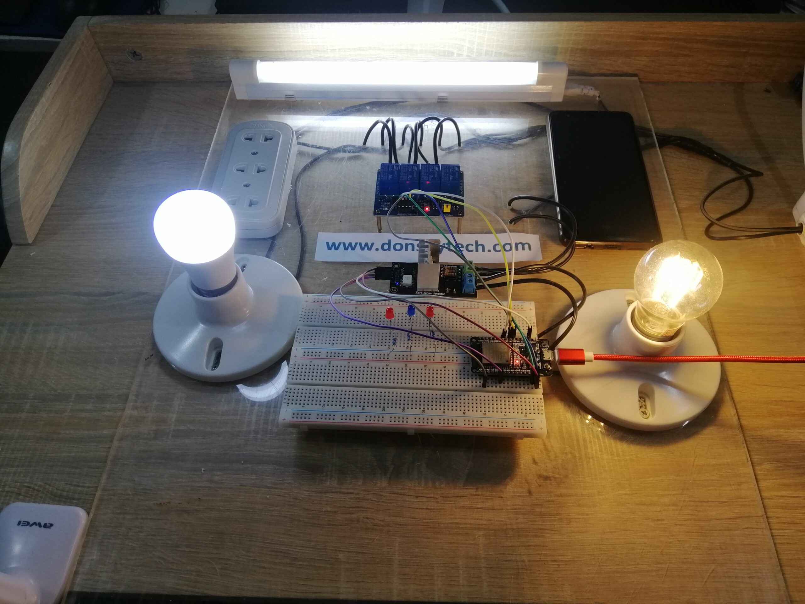
In this post, I am going to show you how I created my ESP32 Home Automation Project. In addition, I built the whole project using the PlatformIO IDE. Also, I created my custom home automation prototype using an acrylic sheet for better wiring of my AC loads. I then set up my ESP32 as a web server to control my different load components.
For a Demo of the project please see the following video on my youtube channel.
Schematic/Wiring Diagram of ESP32 Home Automation Project
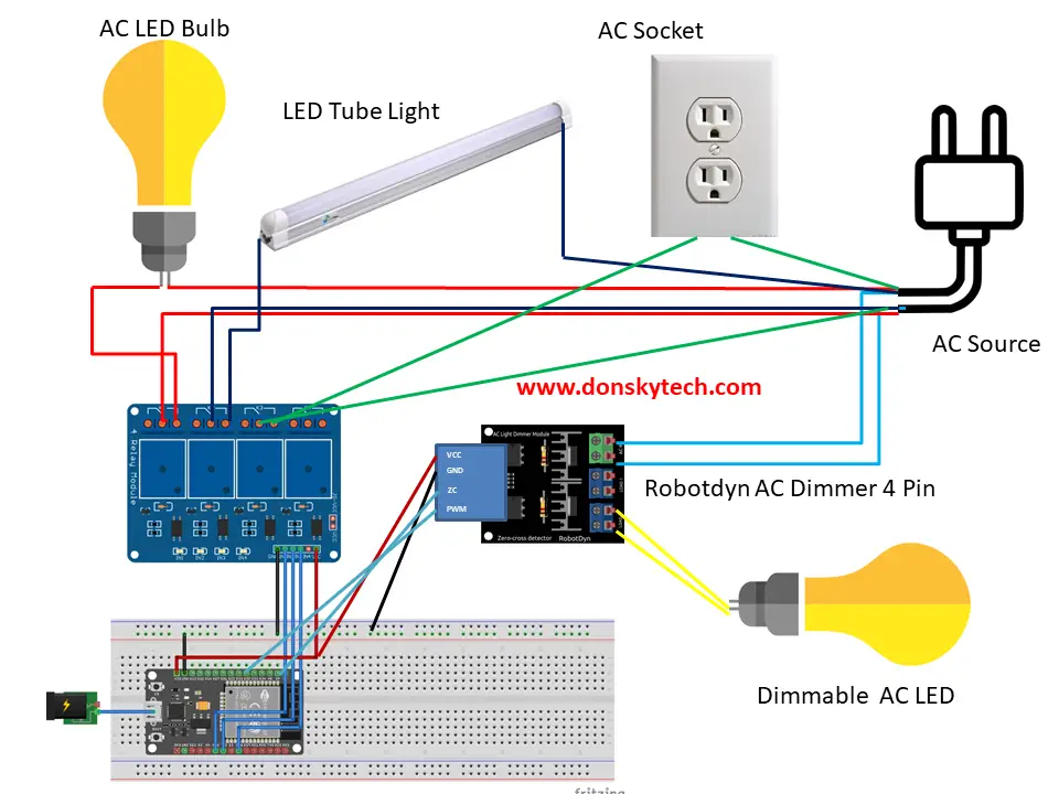
The image above is the schematic diagram of my ESP32 Home Automation that I built using PlatformIO IDE. I could not find the different Fritzing parts so I manually edited the connection in my image 🙂
If the following wiring diagram seems confusing then follow the following connections
| ESP32 | Relay |
| GPIO16 | IN1 |
| GPIO17 | IN2 |
| GPIO18 | IN3 |
| VIN | VCC |
| GND | GND |
I could not find a fritzing part for the Robotdyn AC Dimmer that has 4 pins with a configurable Zero Cross and Output Pin so I just edited the pinout in my image. You can follow the following connection details
| ESP32 | Robotdyn AC Dimmer |
| GPIO32 | PWM Pin |
| GPIO36 | Zero Cross Pin |
| VIN | VCC |
| GND | GND |
For the dimmable LED bulb just connect it to any of the output pins of your Robotdyn AC Dimmer.
The connection from the Relay output to the AC Load goes like the image above. Just connect one line directly to the AC Load then connect the other AC Line to the Common Connection of your Relay then connect the Normally Open pin into the AC Load.
Note: Be very careful when connecting AC Load as you could be electrocuted if there is an improper connection. Ask for help if you don’t know what you are doing!
donsky
Using PlatformIO IDE
I used Visual Studio Code with the PlatformIO extension installed in developing this project. If you are in Windows and have not yet installed Visual Studio Code then you can check my post about how to Install Visual Studio Code or VSCode in Windows. If you are not familiar with PlatformIO then please read this PlatformIO Tutorial for Arduino Development where I detailed how to get started with development using the PlatformIO IDE extension
ESP32 Web Server
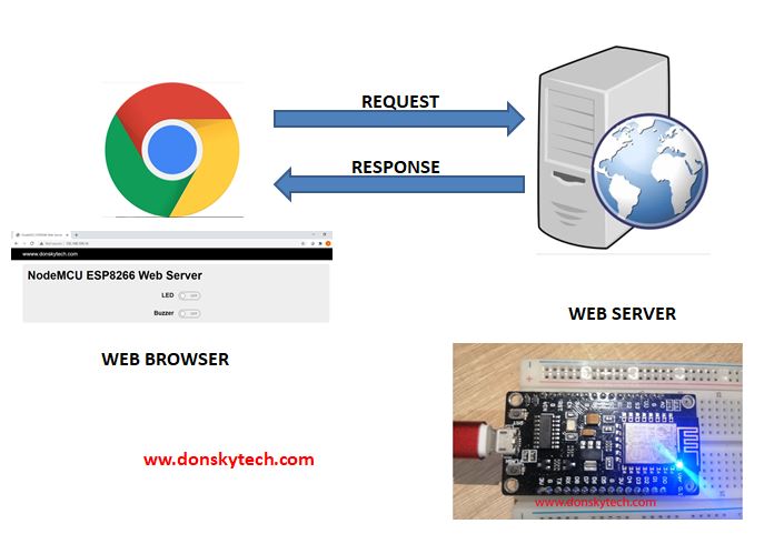
In order for us to control our AC load then we have configured our ESP32 as a Web Server to be able to respond to HTTP request coming in from the browser. So by using browsers in your laptop or mobile phone then you can control our Home Automation Project. If you are not familiar with how Web Server works then click the following tutorial that I have created about that.
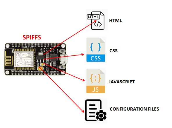
We have deployed our application in the ESP32 Serial Peripheral Interface Flash File System (SPIFFS). Our application user interface is composed of HTML pages with CSS and Javascript for styling and handling user interaction. It is much better to use SPIFFS than putting all of our pages in arduino variables.
Please see the next section where I discussed how the User Interface for our web server is structured.
Code in PlatformIO
The code for this project is in my GitHub account. You can either download it as a zip file or clone it if you know git.
git clone https://github.com/donskytech/platformio-projects.git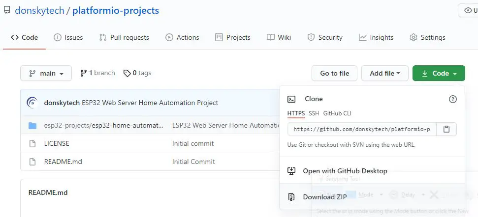
Open your Visual Studio Code and you can click File->Add Folder to Workspace. Then, select the folder where you have downloaded or clone my GitHub project.
I am using Windows and I have it cloned in this folder.
C:\git\platformio-projects\esp32-projects\esp32-home-automation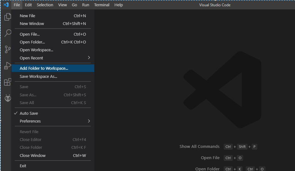
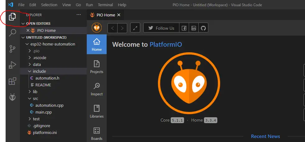
If everything goes well then the code should be imported into your Visual Studio Code. Click the explorer tab at the far left to see the code.
The one thing I like about using PlatformIO IDE is the ease by which we configure our dependencies. Whereas in Arduino IDE, we configure our dependent files using the library manager, in PlatformIO we set the dependencies using the platformio.ini file or add them automatically using the Library Manager.
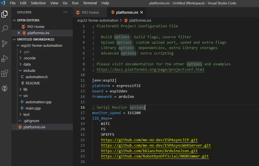
If you click the platformio.ini file, you will notice that the following libraries are configured in the lib_deps section. This particular ESP32 Home Automation Project has dependencies on the following projects. With PlatformIO, we don’t need to manually add anything as these dependencies are downloaded and configured to us automatically. Cool is it?
- https://github.com/me-no-dev/ESPAsyncTCP.git
- https://github.com/me-no-dev/ESPAsyncWebServer.git
- https://github.com/bblanchon/ArduinoJson.git
- https://github.com/RobotDynOfficial/RBDDimmer.git
HTML/CSS/Javascript
All static files like HTML, Cascading Style Sheets (CSS), and Javascript files are located inside the data folder of your PlatformIO projects. All these files need to be uploaded to the ESP32 SPIFFS using the PlatformIO Upload Task.
Our ESP32 Home Automation Project contains only 1 HTML page called index.html and it contains all the necessary user interfaces that we need. You can view the whole files on my GitHub page.
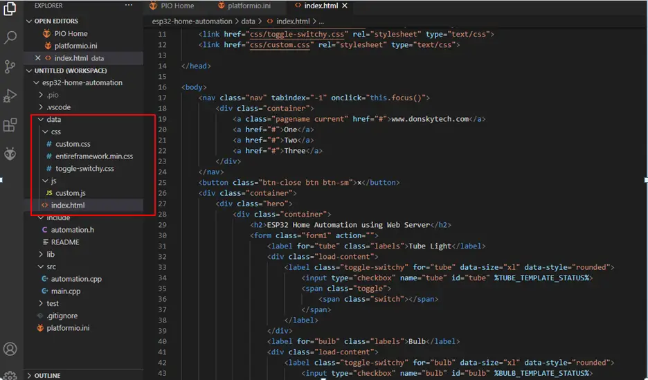
index.html
The index.html contains the main user interface of our project. It may seem hard to digest at once so let us discuss each line one by one.
<!DOCTYPE html>
<html>

<head>
    <meta charset="UTF-8">
    <meta name="viewport" content="width=device-width, initial-scale=1">

    <title>ESP32 Home Automation</title>

    <link href="css/entireframework.min.css" rel="stylesheet" type="text/css">
    <link href="css/toggle-switchy.css" rel="stylesheet" type="text/css">
    <link href="css/custom.css" rel="stylesheet" type="text/css">

</head>

<body>
    <nav class="nav" tabindex="-1" onclick="this.focus()">
        <div class="container">
            <a class="pagename current" href="#">www.donskytech.com</a>
            <a href="#">One</a>
            <a href="#">Two</a>
            <a href="#">Three</a>
        </div>
    </nav>
    <button class="btn-close btn btn-sm">×</button>
    <div class="container">
        <div class="hero">
            <div class="container">
                <h2>ESP32 Home Automation using Web Server</h2>
                <form class="form1" action="">
                    <label for="tube" class="labels">Tube Light</label>
                    <div class="load-content">
                        <label class="toggle-switchy" for="tube" data-size="xl" data-style="rounded">
                            <input type="checkbox" name="tube" id="tube" %TUBE_TEMPLATE_STATUS%>
                            <span class="toggle">
                                <span class="switch"></span>
                            </span>
                        </label>
                    </div>
                    <label for="bulb" class="labels">Bulb</label>
                    <div class="load-content">
                        <label class="toggle-switchy" for="bulb" data-size="xl" data-style="rounded">
                            <input type="checkbox" name="bulb" id="bulb" %BULB_TEMPLATE_STATUS%>
                            <span class="toggle">
                                <span class="switch"></span>
                            </span>
                        </label>
                    </div>
                    <label for="socket" class="labels">Socket</label>
                    <div class="load-content">
                        <label class="toggle-switchy" for="socket" data-size="xl" data-style="rounded">
                            <input type="checkbox" name="socket" id="socket" %SOCKET_TEMPLATE_STATUS%>
                            <span class="toggle">
                                <span class="switch"></span>
                            </span>

                        </label>
                    </div>

                    <div class="slider-content">
                        <div class="center">
                            <label for="dimmable" class="simple-labels">Dimmable Bulb:</label>
                            <span id="dim-value">%DIMMER_VALUE%</span>
                        </div>

                        <div id="container" class="center">
                            <input type="range" id="dim-value-slider" step=5 value="%DIMMER_VALUE%">
                        </div>
                    </div>
                </form>
            </div>


            <script src="js/custom.js"></script>
        </div>
    </div>
</body>

</html>
<head>
<meta charset="UTF-8">
<meta name="viewport" content="width=device-width, initial-scale=1">
<title>ESP32 Home Automation</title>
<link href="css/entireframework.min.css" rel="stylesheet" type="text/css">
<link href="css/toggle-switchy.css" rel="stylesheet" type="text/css">
<link href="css/custom.css" rel="stylesheet" type="text/css">
</head>The head section contains all the meta tags which are needed for proper rendering in mobile browsers. It contains the title tag as well to discuss our project. Also, our index.html needs 3 additional files to handle the styling and user interaction.
- entireframework.min.css – is the main stylesheet that I used using the popular mincss library.
- toggle-switchy – is a CSS library that you can use to convert your checkbox into a toggle type interface
- custom.css – is my custom styling file
            <script src="js/custom.js"></script>
        </div>
    </div>
</body>
Before the end of my body tag, I imported my custom.js file which I have used to handle events when the user toggles my checkbox.
    <nav class="nav" tabindex="-1" onclick="this.focus()">
        <div class="container">
            <a class="pagename current" href="#">www.donskytech.com</a>
            <a href="#">One</a>
            <a href="#">Two</a>
            <a href="#">Three</a>
        </div>
    </nav>
The code above is just for my navigation and showing my site page. 🙂
                <form class="form1" action="">
                    <label for="tube" class="labels">Tube Light</label>
                    <div class="load-content">
                        <label class="toggle-switchy" for="tube" data-size="xl" data-style="rounded">
                            <input type="checkbox" name="tube" id="tube" %TUBE_TEMPLATE_STATUS%>
                            <span class="toggle">
                                <span class="switch"></span>
                            </span>
                        </label>
                    </div>
                    <label for="bulb" class="labels">Bulb</label>
                    <div class="load-content">
                        <label class="toggle-switchy" for="bulb" data-size="xl" data-style="rounded">
                            <input type="checkbox" name="bulb" id="bulb" %BULB_TEMPLATE_STATUS%>
                            <span class="toggle">
                                <span class="switch"></span>
                            </span>
                        </label>
                    </div>
                    <label for="socket" class="labels">Socket</label>
                    <div class="load-content">
                        <label class="toggle-switchy" for="socket" data-size="xl" data-style="rounded">
                            <input type="checkbox" name="socket" id="socket" %SOCKET_TEMPLATE_STATUS%>
                            <span class="toggle">
                                <span class="switch"></span>
                            </span>

                        </label>
                    </div>

                    <div class="slider-content">
                        <div class="center">
                            <label for="dimmable" class="simple-labels">Dimmable Bulb:</label>
                            <span id="dim-value">%DIMMER_VALUE%</span>
                        </div>

                        <div id="container" class="center">
                            <input type="range" id="dim-value-slider" step=5 value="%DIMMER_VALUE%">
                        </div>
                    </div>
                </form>
Now this is the most important part of my page. Each checkbox is styled to look like a toggle box by the toggle-switchy CSS library. It is important to take note as well of the following “template” construct. They are template variables that will be replaced later by the template processing engine of our ESPAsyncWebServer .
- %TUBE_TEMPLATE_STATUS%
- %BULB_TEMPLATE_STATUS%
- %SOCKET_TEMPLATE_STATUS%
- %DIMMER_VALUE%
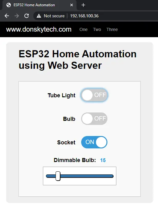
When the HTML/CSS/Javascript is processed by the browser then it would be rendered like the below user interface. This is how we are going to interact with our ESP32 Home Automation Project and control our AC load using our mobile phone browsers.
custom.js
The custom.js is our custom javascript file that will handle the interaction between our web pages and the user. So for example, if the user toggles the bulb checkbox then it should update the value of our user interface and toggle the value of the GPIO pin thru the digitalWrite function.
// Locate the 3 checkbox
const tube = document.querySelector('#tube');
const bulb = document.querySelector('#bulb');
const socket = document.querySelector('#socket');

// Add event Listener to the 3 checkbox
tube.addEventListener('change', toggleStatus);
bulb.addEventListener('change', toggleStatus);
socket.addEventListener('change', toggleStatus);

async function sendRequestToServer(url) {
  try {
    let res = await fetch(url);
    return await res.json();
  } catch (error) {
    console.log(error);
  }
}

async function toggleStatus(e) {
  let sourceElementName = e.target.name;
  let url = '/toggle/' + sourceElementName + '?status=';
  if (e.target.checked) {
    url += 'true';
  } else {
    url += 'false';
  }
  console.log("Sending to " + url);

  let response = await sendRequestToServer(url);

  console.log(response);
}

const slider = document.querySelector("#dim-value-slider");
const output = document.querySelector("#dim-value");
// Add event on range change
slider.addEventListener('input', updateDimmerValue);

async function updateDimmerValue(e) {
  //send request
  let url = '/dimmer/change' + '?value=' + slider.value;
  console.log("Sending to " + url);

  let response = await sendRequestToServer(url);

  console.log(response);

  //update dimmer value
  output.innerHTML = slider.value;
}
The code above uses the Fetch API which I have chosen instead of using the XMLHTTPRequest object which is a rather old API. Upon selecting the element from the DOM and attaching the function handler to the event then we are going to send a JSON request to our web server then process the response and refresh our web page. In addition, we are using the javascript async/await syntax to handle the waiting/processing of our JSON request.
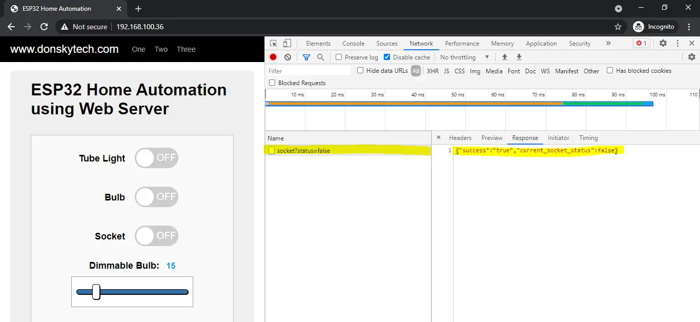
Later if you want to see the JSON request being sent out by our user interface then click F12 in your browser then go to the Network tab. You can do this once we have deployed our application to ESP32. if you toggle any of our switches then under the hood a request is being sent out to our ESP32 Asynchronous Web Server that has the control to our GPIO.
That is all there is to know about our HTML Pages and how we handle the user interaction with our pages.
We will now proceed to the important part of this workspace highlighted below. These 3 files power our ESP32 Home Automation Project. They are the files that power our ESP32 Web Servers and do the following:
- Create a Web Server and listen to HTTP requests coming from the browser
- Save the current status of our AutomationProto class so that even if we access this in multiple browsers then we would still get the same status.
- Update the value of our GPIO Pins
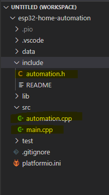
I separated my code into a header file and a CPP file to further clean up the structure of my code. The header file will contain the skeleton of our project while the CPP file will show the implementation. In our case, “automation.h” is our header file, and “automation.cpp” is our CPP file.
automation.h
I tried to follow object oriented programming in creating this project so I represented my AutomationProto as a class. Please try to read the link in wikipedia if you are unfamiliar on how Object Oriented programming works.
This C++ header files contains the class that will control our project. You might ask, why do we need a class? You might think of a class as a “blueprint” for your house. Using that blueprint then we could re-create your house again. We are representing our Home Automation as a class to keep everything in one part of the code.
Furthermore, it contains the imported header file needed to power our dimmable lamp. I have used the Robotdyn AC Dimmer library so I have imported it here.
This class also represents the status of our AC Loads so you would see boolean property for each AC Load. One property represents the tube light(m_tube), the socket(m_socket), the bulb(m_bulb) and the dimmer lamp value(m_dimValue).
It also contains all the getters and setters property to alter the private variables of our class. In the “main.cpp“ file, you will see how this class is being imported.
#ifndef AUTOMATION_H
#define AUTOMATION_H
#include <Arduino.h>
#include <RBDdimmer.h>

class AutomationProto
{
private:
    bool m_tube;
    bool m_socket;
    bool m_bulb;
    int m_dimValue;
    dimmerLamp m_dimmer;

public:
    AutomationProto();
    void init();
    void setTubeStatus(bool status);
    bool isTubeOn();
    void setSocketStatus(bool status);
    bool isSocketOn();
    void setBulbStatus(bool status);
    bool isBulbOn();
    void setDimmerValue(int value);
    int getDimmerValue();

    // Static Constant Pin
    static int const TUBE_PIN;
    static int const BULB_PIN;
    static int const SOCKET_PIN;

    // Dimmer Constant Pin
    static int const DIMMER_ZERO_CROSS_PIN;
    static int const DIMMER_OUTPUT_PIN;
};

#endif
automation.cpp
The “automation.cpp” contains the implementation of the code. It also defines the ESP32 pin to control our power relay.
In our case here, the following are the pin assignments
- Tube Pin – GPIO 16
- Bulb Pin – GPIO 17
- Socket Pin – GPIO 18
- Dimmer Output Pin – GPIO 32
- Dimmer Zero Cross Pin – GPIO 36
I have added relevant comments for each line of code so as to make the code readable.
#include "automation.h"

AutomationProto::AutomationProto() : m_tube{false}, m_socket{false}, m_bulb{false},
                                     m_dimValue{0}, m_dimmer(DIMMER_OUTPUT_PIN, DIMMER_ZERO_CROSS_PIN)
{
};

// Pin configuration for tube/bulb/socket
int const AutomationProto::TUBE_PIN = 16;
int const AutomationProto::BULB_PIN = 17;
int const AutomationProto::SOCKET_PIN = 18;

// Dimmer Pin implementation
int const AutomationProto::DIMMER_OUTPUT_PIN = 32;
int const AutomationProto::DIMMER_ZERO_CROSS_PIN = 36;

void AutomationProto::init()
{
    pinMode(TUBE_PIN, OUTPUT);
    pinMode(BULB_PIN, OUTPUT);
    pinMode(SOCKET_PIN, OUTPUT);

    // Relays are active low so we set it to HIGH
    digitalWrite(TUBE_PIN, HIGH);
    digitalWrite(BULB_PIN, HIGH);
    digitalWrite(SOCKET_PIN, HIGH);

    // Begin dimmer setup
    m_dimmer.begin(NORMAL_MODE, ON); //dimmer initialisation: name.begin(MODE, STATE)
}

// Getters and Setters
void AutomationProto::setTubeStatus(bool status)
{
    m_tube = status;
    digitalWrite(TUBE_PIN, !status);
}

bool AutomationProto::isTubeOn()
{
    return m_tube;
}
void AutomationProto::setSocketStatus(bool status)
{
    m_socket = status;
    digitalWrite(SOCKET_PIN, !status);
}
bool AutomationProto::isSocketOn()
{
    return m_socket;
}
void AutomationProto::setBulbStatus(bool status)
{
    m_bulb = status;
    digitalWrite(BULB_PIN, !status);
}
bool AutomationProto::isBulbOn()
{
    return m_bulb;
}

void AutomationProto::setDimmerValue(int value)
{
    m_dimValue = value;
    m_dimmer.setPower(value);
}
int AutomationProto::getDimmerValue()
{
    return m_dimValue;
}
Let us try to break out each line of code for better understanding.
#include "automation.h"

AutomationProto::AutomationProto() : m_tube{false}, m_socket{false}, m_bulb{false},
                                     m_dimValue{0}, m_dimmer(DIMMER_OUTPUT_PIN, DIMMER_ZERO_CROSS_PIN)
{
};
The line of code above imports our “automation.h” and defines the C++ constructor for our AutomationProto class. We have initialized all variables to false to represent “OFF” state. If it is set to true then it represents “ON” state.
// Pin configuration for tube/bulb/socket
int const AutomationProto::TUBE_PIN = 16;
int const AutomationProto::BULB_PIN = 17;
int const AutomationProto::SOCKET_PIN = 18;

// Dimmer Pin implementation
int const AutomationProto::DIMMER_OUTPUT_PIN = 32;
int const AutomationProto::DIMMER_ZERO_CROSS_PIN = 36;
The code above represents our GPIO Pin assignment.
void AutomationProto::init()
{
    pinMode(TUBE_PIN, OUTPUT);
    pinMode(BULB_PIN, OUTPUT);
    pinMode(SOCKET_PIN, OUTPUT);

    // Relays are active low so we set it to HIGH
    digitalWrite(TUBE_PIN, HIGH);
    digitalWrite(BULB_PIN, HIGH);
    digitalWrite(SOCKET_PIN, HIGH);

    // Begin dimmer setup
    m_dimmer.begin(NORMAL_MODE, ON); //dimmer initialisation: name.begin(MODE, STATE)
}
The code above is a custom method that will initialize our AutomationProto class and set all the GPIO output using the Arduino digitalWrite command. The dimmer class is also initialized in this method.
// Getters and Setters
void AutomationProto::setTubeStatus(bool status)
{
    m_tube = status;
    digitalWrite(TUBE_PIN, !status);
}

bool AutomationProto::isTubeOn()
{
    return m_tube;
}
Each AC load is represented by a getter and setter method which would set the private values of our class. In addition, we call the digitalWrite code in here so as to turn on or off our GPIO depending.
main.cpp
This is the main class of this home automation project and is responsible for servicing the HTTP Request coming from the browser and handling the interface to our hardware. Let’s analyze each part of the code to understand what it is doing in detail.
#ifdef ESP32
#include <WiFi.h>
#include <AsyncTCP.h>
#elif defined(ESP8266)
#include <ESP8266WiFi.h>
#include <ESPAsyncTCP.h>
#endif
#include <ESPAsyncWebServer.h>
#include "AsyncJson.h"
#include "ArduinoJson.h"
#include "SPIFFS.h"
#include "automation.h"

// Enter your User ID and Password for your wifi connection
const char *ssid = "donsky";
const char *password = "donsky";

AsyncWebServer server(80);

// Import our Automation Proto Class
AutomationProto proto;

// Processor for index page template
String indexPageProcessor(const String &var)
{
    String status = "";
    if (var == "TUBE_TEMPLATE_STATUS")
    {
        if (proto.isTubeOn())
        {
            status = "checked";
        }
    }
    else if (var == "BULB_TEMPLATE_STATUS")
    {
        if (proto.isBulbOn())
        {
            status = "checked";
        }
    }
    else if (var == "SOCKET_TEMPLATE_STATUS")
    {
        if (proto.isSocketOn())
        {
            status = "checked";
        }
    }
    else if (var == "DIMMER_VALUE")
    {
        status = String(proto.getDimmerValue());
        Serial.print("Dimmer Value: ");
        Serial.println(status);
    }
    return status;
}

void notFound(AsyncWebServerRequest *request)
{
    request->send(404, "text/plain", "Not found");
}

void setup()
{

    Serial.begin(115200);
    Serial.println("Connecting to ");
    Serial.println(ssid);
    WiFi.mode(WIFI_STA);
    WiFi.begin(ssid, password);
    if (WiFi.waitForConnectResult() != WL_CONNECTED)
    {
        Serial.printf("WiFi Failed!\n");
        return;
    }

    Serial.print("IP Address: ");
    Serial.println(WiFi.localIP());

    // Initialize SPIFFS
    if (!SPIFFS.begin(true))
    {
        Serial.println("An Error has occurred while mounting SPIFFS");
        return;
    }

    //initialize our automation proto project
    proto.init();


    server.on("/", HTTP_GET, [](AsyncWebServerRequest *request) {
        Serial.println("Requesting index page...");
        request->send(SPIFFS, "/index.html", "text/html", false, indexPageProcessor);
    });

    // Route to load entireframework.min.css file
    server.on("/css/entireframework.min.css", HTTP_GET, [](AsyncWebServerRequest *request) {
        request->send(SPIFFS, "/css/entireframework.min.css", "text/css");
    });

    // Route to load toggle-switchy.css file
    server.on("/css/toggle-switchy.css", HTTP_GET, [](AsyncWebServerRequest *request) {
        request->send(SPIFFS, "/css/toggle-switchy.css", "text/css");
    });

    // Route to load custom.css file
    server.on("/css/custom.css", HTTP_GET, [](AsyncWebServerRequest *request) {
        request->send(SPIFFS, "/css/custom.css", "text/css");
    });

    // Route to load custom.js file
    server.on("/js/custom.js", HTTP_GET, [](AsyncWebServerRequest *request) {
        request->send(SPIFFS, "/js/custom.js", "text/javascript");
    });

    // server toggle request for "tube"
    server.on("/toggle/tube", HTTP_GET, [](AsyncWebServerRequest *request) {
        StaticJsonDocument<100> data;
        if (request->hasParam("status"))
        {
            String status = request->getParam("status")->value();
            bool tubeStatus = (status == "true");
            proto.setTubeStatus(tubeStatus);
            data["success"] = "true";
            data["current_tube_status"] = proto.isTubeOn();
        }
        else
        {
            data["isError"] = "true";
            data["error_description"] = "No tube status parameter was sent by the client!";
        }

        AsyncResponseStream *response = request->beginResponseStream("application/json");
        serializeJson(data, *response);
        request->send(response);
    });

    // server toggle request for "bulb"
    server.on("/toggle/bulb", HTTP_GET, [](AsyncWebServerRequest *request) {
        StaticJsonDocument<100> data;
        if (request->hasParam("status"))
        {
            String status = request->getParam("status")->value();
            bool bulbStatus = (status == "true");
            proto.setBulbStatus(bulbStatus);
            data["success"] = "true";
            data["current_bulb_status"] = proto.isBulbOn();
        }
        else
        {
            data["isError"] = "true";
            data["error_description"] = "No bulb status parameter was sent by the client!";
        }

        AsyncResponseStream *response = request->beginResponseStream("application/json");
        serializeJson(data, *response);
        request->send(response);
    });

    // server toggle request for "socket"
    server.on("/toggle/socket", HTTP_GET, [](AsyncWebServerRequest *request) {
        StaticJsonDocument<100> data;
        if (request->hasParam("status"))
        {
            String status = request->getParam("status")->value();
            bool socketStatus = (status == "true");
            proto.setSocketStatus(socketStatus);
            data["success"] = "true";
            data["current_socket_status"] = proto.isSocketOn();
        }
        else
        {
            data["isError"] = "true";
            data["error_description"] = "No socket status parameter was sent by the client!";
        }

        AsyncResponseStream *response = request->beginResponseStream("application/json");
        serializeJson(data, *response);
        request->send(response);
    });

    // server toggle request for "dimmer"
    server.on("/dimmer/change", HTTP_GET, [](AsyncWebServerRequest *request) {
        StaticJsonDocument<100> data;
        if (request->hasParam("value"))
        {
            String value = request->getParam("value")->value();
            proto.setDimmerValue(value.toInt());
            data["success"] = "true";
            data["current_dimmer_value"] = proto.getDimmerValue();
        }
        else
        {
            data["isError"] = "true";
            data["error_description"] = "No dimmer value parameter was sent by the client!";
        }

        AsyncResponseStream *response = request->beginResponseStream("application/json");
        serializeJson(data, *response);
        request->send(response);
    });

    server.onNotFound(notFound);

    server.begin();
}

void loop()
{
}
#ifdef ESP32
#include <WiFi.h>
#include <AsyncTCP.h>
#elif defined(ESP8266)
#include <ESP8266WiFi.h>
#include <ESPAsyncTCP.h>
#endif
#include <ESPAsyncWebServer.h>
#include "AsyncJson.h"
#include "ArduinoJson.h"
#include "SPIFFS.h"
#include "automation.h"
These are our include statements that will tell which header file we will be needing.
// Enter your User ID and Password for your wifi connection
const char *ssid = "donsky";
const char *password = "donsky";
Update the following network connection username and password to match the network credential of your wifi.
AsyncWebServer server(80);

// Import our Automation Proto Class
AutomationProto proto;
We define our ESP32 Web server that will listen at the default port 80 and import our AutomationProto class.
// Processor for index page template
String indexPageProcessor(const String &var)
{
    String status = "";
    if (var == "TUBE_TEMPLATE_STATUS")
    {
        if (proto.isTubeOn())
        {
            status = "checked";
        }
    }
    else if (var == "BULB_TEMPLATE_STATUS")
    {
        if (proto.isBulbOn())
        {
            status = "checked";
        }
    }
    else if (var == "SOCKET_TEMPLATE_STATUS")
    {
        if (proto.isSocketOn())
        {
            status = "checked";
        }
    }
    else if (var == "DIMMER_VALUE")
    {
        status = String(proto.getDimmerValue());
        Serial.print("Dimmer Value: ");
        Serial.println(status);
    }
    return status;
}

    server.on("/", HTTP_GET, [](AsyncWebServerRequest *request) {
        Serial.println("Requesting index page...");
        request->send(SPIFFS, "/index.html", "text/html", false, indexPageProcessor);
    });
The code above is our “template” processor function and will set the attribute “checked” on a checkbox. Remember in our discussion above about the index.html template variables, they are being processed and replaced in this function. This function is called on the “/” root or index.html call.
void notFound(AsyncWebServerRequest *request)
{
    request->send(404, "text/plain", "Not found");
}

server.onNotFound(notFound);
The function above is called when a request is sent to the server and the server does not know how to respond.
void setup()
{

    Serial.begin(115200);
    Serial.println("Connecting to ");
    Serial.println(ssid);
    WiFi.mode(WIFI_STA);
    WiFi.begin(ssid, password);
    if (WiFi.waitForConnectResult() != WL_CONNECTED)
    {
        Serial.printf("WiFi Failed!\n");
        return;
    }

    Serial.print("IP Address: ");
    Serial.println(WiFi.localIP());

    // Initialize SPIFFS
    if (!SPIFFS.begin(true))
    {
        Serial.println("An Error has occurred while mounting SPIFFS");
        return;
    }

    //initialize our automation proto project
    proto.init();
The code above is the beginning of our setup() function. We initialize our serial object and begin connecting to our wifi. Afterwhich, we begin initializing our SPIFFS. If all goes well then we initialize our class with the proto.init() function call.
server.on("/", HTTP_GET, [](AsyncWebServerRequest *request) {
        Serial.println("Requesting index page...");
        request->send(SPIFFS, "/index.html", "text/html", false, indexPageProcessor);
    });

    // Route to load entireframework.min.css file
    server.on("/css/entireframework.min.css", HTTP_GET, [](AsyncWebServerRequest *request) {
        request->send(SPIFFS, "/css/entireframework.min.css", "text/css");
    });

    // Route to load toggle-switchy.css file
    server.on("/css/toggle-switchy.css", HTTP_GET, [](AsyncWebServerRequest *request) {
        request->send(SPIFFS, "/css/toggle-switchy.css", "text/css");
    });

    // Route to load custom.css file
    server.on("/css/custom.css", HTTP_GET, [](AsyncWebServerRequest *request) {
        request->send(SPIFFS, "/css/custom.css", "text/css");
    });

    // Route to load custom.js file
    server.on("/js/custom.js", HTTP_GET, [](AsyncWebServerRequest *request) {
        request->send(SPIFFS, "/js/custom.js", "text/javascript");
    });
The following code is our setup function assignment when our static resources are being requested and are loaded from our SPIFFS.
    // server toggle request for "tube"
    server.on("/toggle/tube", HTTP_GET, [](AsyncWebServerRequest *request) {
        StaticJsonDocument<100> data;
        if (request->hasParam("status"))
        {
            String status = request->getParam("status")->value();
            bool tubeStatus = (status == "true");
            proto.setTubeStatus(tubeStatus);
            data["success"] = "true";
            data["current_tube_status"] = proto.isTubeOn();
        }
        else
        {
            data["isError"] = "true";
            data["error_description"] = "No tube status parameter was sent by the client!";
        }

        AsyncResponseStream *response = request->beginResponseStream("application/json");
        serializeJson(data, *response);
        request->send(response);
    });

    // server toggle request for "bulb"
    server.on("/toggle/bulb", HTTP_GET, [](AsyncWebServerRequest *request) {
        StaticJsonDocument<100> data;
        if (request->hasParam("status"))
        {
            String status = request->getParam("status")->value();
            bool bulbStatus = (status == "true");
            proto.setBulbStatus(bulbStatus);
            data["success"] = "true";
            data["current_bulb_status"] = proto.isBulbOn();
        }
        else
        {
            data["isError"] = "true";
            data["error_description"] = "No bulb status parameter was sent by the client!";
        }

        AsyncResponseStream *response = request->beginResponseStream("application/json");
        serializeJson(data, *response);
        request->send(response);
    });

    // server toggle request for "socket"
    server.on("/toggle/socket", HTTP_GET, [](AsyncWebServerRequest *request) {
        StaticJsonDocument<100> data;
        if (request->hasParam("status"))
        {
            String status = request->getParam("status")->value();
            bool socketStatus = (status == "true");
            proto.setSocketStatus(socketStatus);
            data["success"] = "true";
            data["current_socket_status"] = proto.isSocketOn();
        }
        else
        {
            data["isError"] = "true";
            data["error_description"] = "No socket status parameter was sent by the client!";
        }

        AsyncResponseStream *response = request->beginResponseStream("application/json");
        serializeJson(data, *response);
        request->send(response);
    });

    // server toggle request for "dimmer"
    server.on("/dimmer/change", HTTP_GET, [](AsyncWebServerRequest *request) {
        StaticJsonDocument<100> data;
        if (request->hasParam("value"))
        {
            String value = request->getParam("value")->value();
            proto.setDimmerValue(value.toInt());
            data["success"] = "true";
            data["current_dimmer_value"] = proto.getDimmerValue();
        }
        else
        {
            data["isError"] = "true";
            data["error_description"] = "No dimmer value parameter was sent by the client!";
        }

        AsyncResponseStream *response = request->beginResponseStream("application/json");
        serializeJson(data, *response);
        request->send(response);
    });
Now this is the function that responds to a request that has been sent by the browser thru our custom.js. Remember in the image above that when you toggle our checkbox button, a request is being sent under the hood. They are mapped into this function.
For example, “http://<IP-Address>/toggle/socket?status=false” the following HTTP request is being sent when we toggle our socket checkbox. This is mapped to one of the functions above. The status parameter which is either true or false is being processed.
    // server toggle request for "socket"
    server.on("/toggle/socket", HTTP_GET, [](AsyncWebServerRequest *request) {
        StaticJsonDocument<100> data;
        if (request->hasParam("status"))
        {
            String status = request->getParam("status")->value();
            bool socketStatus = (status == "true");
            proto.setSocketStatus(socketStatus);
            data["success"] = "true";
            data["current_socket_status"] = proto.isSocketOn();
        }
        else
        {
            data["isError"] = "true";
            data["error_description"] = "No socket status parameter was sent by the client!";
        }

        AsyncResponseStream *response = request->beginResponseStream("application/json");
        serializeJson(data, *response);
        request->send(response);
    });
In the above code
- Line 2: we map the “/toggle/socket” in this function
- Line 4: we check if the “status” parameter is set to true or false. The following parameter is set by our javascript code. So if we have toggled the checkbox to true then “true” is sent else “false”.
- Line 6-8: we extract the parameter and then set the value to our class AutomationProto
- Lines 9-10: we define a return value to our javascript call.
- Lines 12-16: if the parameter was not defined for any reason then we set the variable “isError” to true together with a message
- Lines 18-20: we send the response thru the ArduinJSON library back to the calling browser
Something similar is happening to the tube light and the bulb button. The only difference is the dimmer bulb.
    // server toggle request for "dimmer"
    server.on("/dimmer/change", HTTP_GET, [](AsyncWebServerRequest *request) {
        StaticJsonDocument<100> data;
        if (request->hasParam("value"))
        {
            String value = request->getParam("value")->value();
            proto.setDimmerValue(value.toInt());
            data["success"] = "true";
            data["current_dimmer_value"] = proto.getDimmerValue();
        }
        else
        {
            data["isError"] = "true";
            data["error_description"] = "No dimmer value parameter was sent by the client!";
        }

        AsyncResponseStream *response = request->beginResponseStream("application/json");
        serializeJson(data, *response);
        request->send(response);
});- Line 2: we listen for the request “/dimmer/change”, this is called when we expand the value of the dimmer.
- Line 6-9: we extract the value of the dimmer input range and set the value of our AutomationProto class thru the call proto.setDimmerValue(value.toInt());
Deployment to your ESP32
If you want to deploy this to your ESP32 then you can do the following from your PlatformIO IDE.
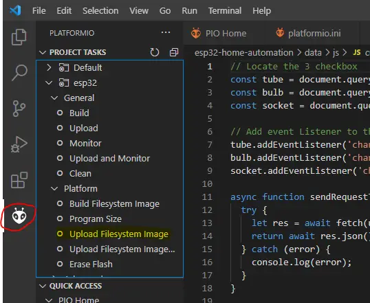
First, we need to upload our static files to the data folder of our project thru the SPIFFS of our ESP32. To do this click the PlatformIO icon and then “Upload Filesystem Image”. If you see the message, “connecting….” you may need to click the boot button in your ESP32.
Next, we upload our code to the flash memory of our ESP32 by clicking the “Upload and Monitor”. If you see the message “connecting….” again then you may need to click the boot button a second time.
Once the monitor of the PlatformIO is displayed, then wait for the message to be displayed like this. If you see it like this then go to your mobile phone browser and type the following ip address. You will now be forwarded to the index.html page.
Connecting to
IP Address: 192.168.100.36
If you see, “WiFi Failed!” message then just click the reset button in your ESP32 and wait for some time for it to initialize again and then retry. Please see my demo video on how to access the user interface of my project.
In summary
And that is all about it. I hope I was able to explain everything you need to know. I really had fun doing this code in PlatformIO. I hope you experience the same thing as well.
If there is any question or doubts then just message me on any of my social media channels.
That’s It!
Happy Exploring!
Leave a Reply