Introduction
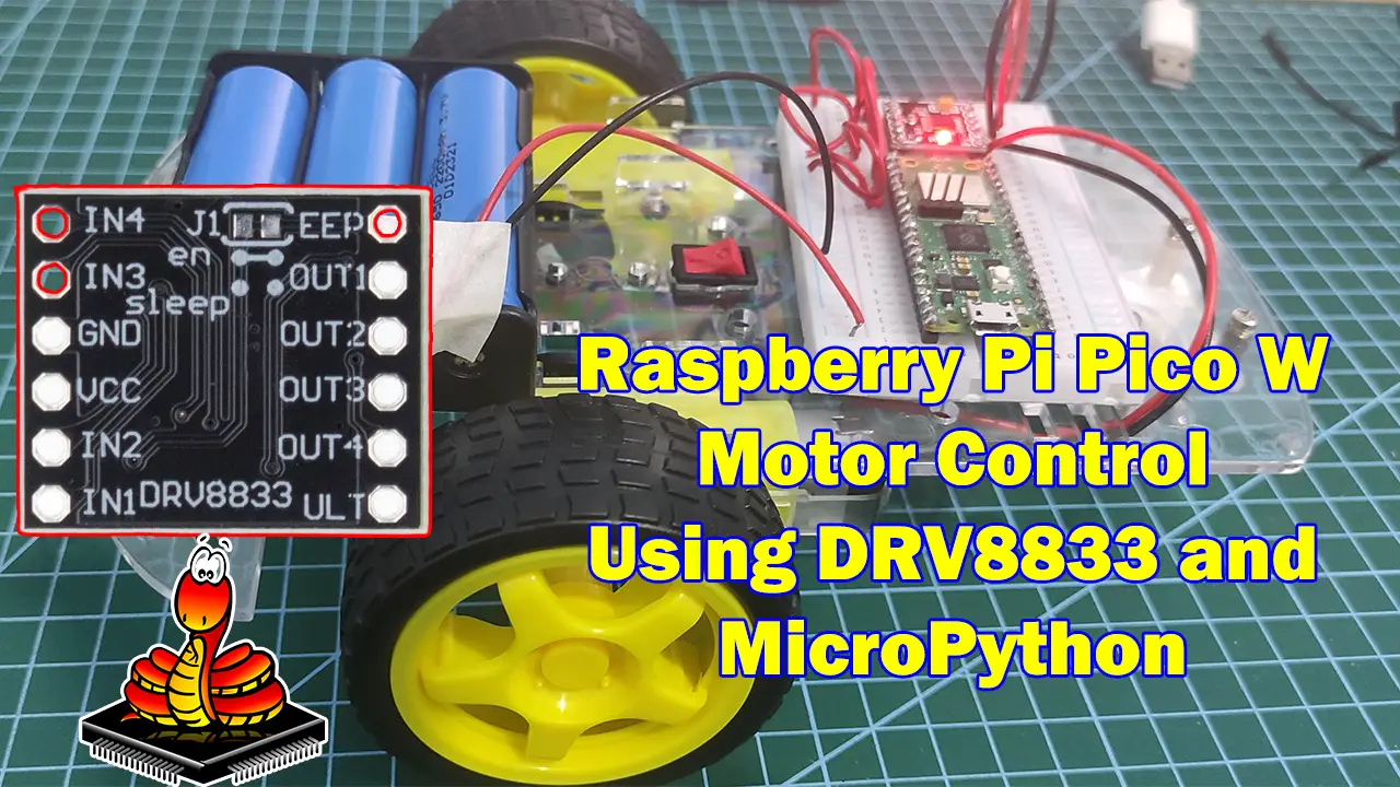
Do you need to control DC Motors for your robotics project using your Raspberry Pi Pico W running MicroPython then this post is for you. I will show you how to interface with the DRV8833 H-Bridge motor driver so that you can adjust the speed and direction of your motors using MicroPython code.
If you want to see a demo of this project then please see the below video or watch it on my YouTube channel.
What are we building?
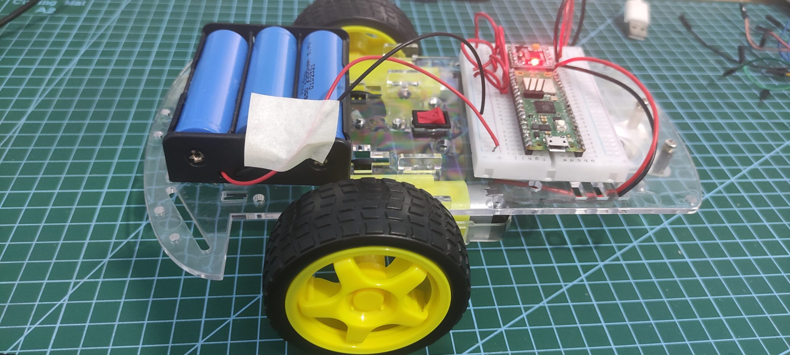
The best way to play around with the capability of the DRV8833 H-Bridge Motor controller with our Raspberry Pi Pico W is to see it in action by building a small robot car and controlling its movement and speed.
In this post, I am not using any MicroPython libraries to drive this module but just simple Pulse Width Modulation (PWM) code. The code here is my own and I have created them thru trial and error and by understanding the datasheet of the DRV8833 module. You may need to adjust some parts of the code if you are using a different motor.
What is DRV8833?
The DRV8833 device is a dual H-Bridge component capable of driving two DC Brush motors, a bipolar stepper motor, solenoids, or other inductive loads. It provides a dual bridge motor driver solution for toys, printers, and other mechatronic applications.
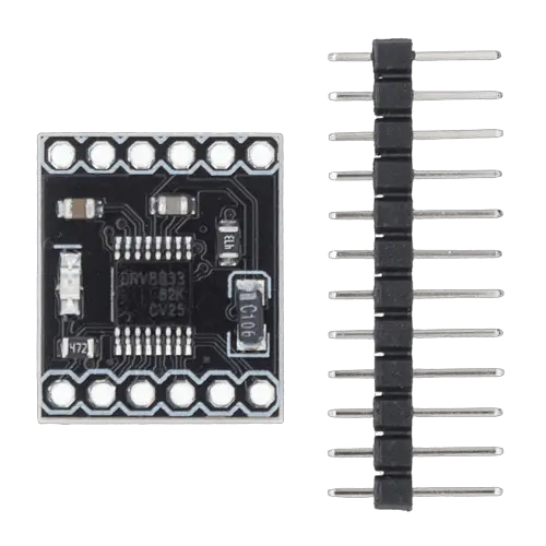
One nice thing about the DRV8833 H-Bridge motor driver is its form factor as compared to the traditional LM298 Motor Driver then it is much smaller but packs the same functionality.
What is an H-Bridge?
But before we continue, let us discuss first what an H-Bridge is and how knowing it will show you how we can control our DC Motors from our program. An H-Bridge is an electronic circuit that switches the polarity of the voltage being applied to a load.
As you can see from the image above, by closing the switches S1 and S4 then the motor moves in a counter-clockwise direction. However, if the S2 and S3 switch is closed then the motor moves in clockwise directions. The switches can be implemented using integrated circuits or mechanical means.
DRV8833 Specifications
The following table list the important specifications for this component.Number of H-Bridge 2 Minimum Voltage 2.7 Peak Output Current 2A Control Mode PWM Operating Temperature -40 to 85 C
DRV8833 Pinout
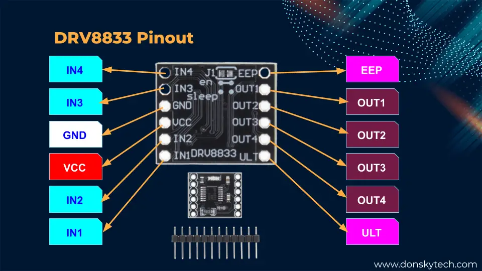
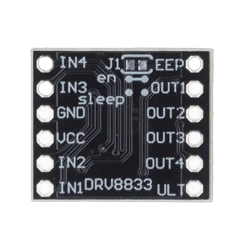
The above image shows the pinout for a typical DRV8833 module.
- IN1/IN2 – Input pins for H-Bridge A
- IN3/IN4 – Input pins for H-Bridge B
- OUT1/OUT2 – Output pins for H-Bridge A
- OUT3/OUT4 – Output pins for H-Bridge B
- EEP – Sleep pin module
- ULT – Fault pin and is set a logic LOW due to overcurrent or temperature heating
- VCC – Supply Pin
- GND – Ground Pin
DRV8833 Input Pin Control
The below table will show you how you can program your Raspberry Pi Pico W for motor control of your DC motors. By setting the input pins value of each motor then it would control the output pins direction. Please see the datasheet of the DRV8833 for more information.IN1 IN2 OUT1 OUT2 Function 0 0 Z Z Coast/Fast Decay 0 1 L H Reverse 1 0 H L Forward 1 1 L L Break/Slow Decay
If you are only interested in turning on or turning off your DC motors then setting the input pin to HIGH or LOW would do the job. Please see the sample code below.
import utime
from machine import Pin

motorIn1 = Pin(16, Pin.OUT)
motorIn2 = Pin(17, Pin.OUT)

def move_forward():
   motorIn1.high()
   motorIn2.low()

def move_backward():
   motorIn1.low()
   motorIn2.high()

def stop():
   motorIn1.low()
   motorIn2.low()

if __name__ == "__main__":
   for i in range(2):
      move_forward()
      utime.sleep(2)
      move_backward()
      utime.sleep(2)
      stop()
As you can see from the code above, I declared the GPIO pins as output pins and just set the value to HIGH and LOW to make the motor move. The movement of the motor depends on the value you set for the input pins.
The code above would move the motor at a constant speed but if you would also like to control the speed of the motor then you would need to use Pulse Width Modulation (PWM) in MicroPython on the input pins.
DRV8833 PWM Control of Motor Speed
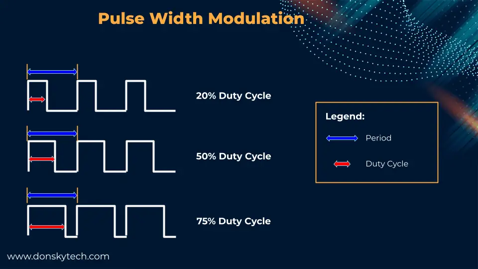
PWM or Pulse Width Modulation is a technique to generate an analog signal from digital pins. The frequency of the signal and the duty cycle dictates the level of the generated output signal.
In order for us to vary the speed of our DC motors using the DRV8833 H-Bridge component then we can alter the PWM values at its input pins.
| IN1 | IN2 | Function |
|---|---|---|
| PWM | 0 | Forward PWM, Fast Decay |
| 1 | PWM | Forward PWM, slow decay |
| 0 | PWM | Reverse PWM, fast decay |
| PWM | 1 | Reverse PWM, slow decay |
As you will see later in the code section, we will use the table above to program our Raspberry Pi Pico W so that we can add motor control functionality to our robot car DC motors.
What are Fast Decay and Slow Decay Mode?
The Fast Decay and Slow Decay function is important to consider for some circuit. For example, if you are operating a robot and it is going to fall from some cliff then choosing a slow decay is better. In this post, I am using fast decay for testing as I just want the motor to just move in a stationary position. Please read the datasheet for more information. When controlling a winding with PWM, when the drive current is interrupted, the inductive nature of the motor requires that the current must continue to flow. This is called recirculation current. To handle this recirculation current, the H-bridge can operate in two different states: fast decay or slow decay. In fast decay mode, the H-bridge is disabled and recirculation current flows through the body diodes; in slow decay, the motor winding is shorted.
This post from AdaFruit explains more about what decay mode is all about as some setup needs this.
As you will see later on in our Building a Raspberry Pi Pico W WiFi Robot Car project, I would be using the Slow Decay mode to instantaneously stop our robot car.
Parts/Components Required
The followings are the components required for this post.
- Raspberry Pi Pico W – Amazon | AliExpress
- DRV8833 – Amazon | AliExpress
- Robot Car Chassis – Amazon | AliExpress | Bangood
- 18650 Batteries – Amazon | AliExpress | Bangood
- Battery Holder – Amazon | AliExpress
- Breadboard – Amazon | AliExpress | Bangood
- Connecting Wires – Amazon | AliExpress | Bangood
Disclosure: These are affiliate links and I will earn small commissions to support my site when you buy through these links.
Prerequisites
You should have installed MicroPython firmware to your Raspberry Pi Pico W. Also, I will be using the Thonny IDE in developing the program for this post. Please see the below posts if you are unfamiliar with how this is done.
Related Content:
How to Install MicroPython Firmware on Raspberry Pi Pico?
MicroPython Development Using Thonny IDE
Wiring/Schematic
The below image is the wiring and schematic for this project. I have used an external battery to power our two DC motors here but the Raspberry Pi Pico W would still be powered by the USB. Later, when we create our own Raspberry Pi Pico W WiFi car then we would power our Pico with the battery also.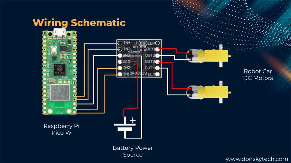
For your reference also, please see the following table.
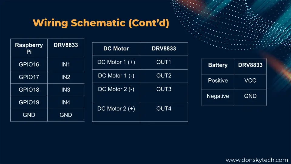
Just make sure that the ground of the Raspberry Pi, DRV8833, and the battery are connected together.
Code
The code for this project is available on my GitHub repository and you can either download it as a zipped file or clone it using Git.
git clone https://github.com/donskytech/micropython-raspberry-pi-pico.git
cd dc-motor-drv8833
There are only 2 files for this project and they are the robot_car.py and the main.py.
robot_car.py
This is the Python file loaded on our Raspberry Pi Pico W that will add motor control to our robot car chassis.
from machine import Pin
from machine import PWM
import utime

'''
Class to represent our robot car
'''
class RobotCar:
    MAX_DUTY_CYCLE = 65535
    MIN_DUTY_CYCLE = 0
    def __init__(self, motor_pins, frequency=20000):
        self.left_motor_pin1 = PWM(Pin(motor_pins[0], mode=Pin.OUT))
        self.left_motor_pin2 = PWM(Pin(motor_pins[1], mode=Pin.OUT))
        self.right_motor_pin1 = PWM(Pin(motor_pins[2], mode=Pin.OUT))
        self.right_motor_pin2 = PWM(Pin(motor_pins[3], mode=Pin.OUT))
        # set PWM frequency
        self.left_motor_pin1.freq(frequency)
        self.left_motor_pin2.freq(frequency)
        self.right_motor_pin1.freq(frequency)
        self.right_motor_pin2.freq(frequency)

        self.current_speed = RobotCar.MAX_DUTY_CYCLE

    def move_forward(self):
        self.left_motor_pin1.duty_u16(self.current_speed)
        self.left_motor_pin2.duty_u16(RobotCar.MIN_DUTY_CYCLE)

        self.right_motor_pin1.duty_u16(self.current_speed)
        self.right_motor_pin2.duty_u16(RobotCar.MIN_DUTY_CYCLE)

    def move_backward(self):
        self.left_motor_pin1.duty_u16(RobotCar.MIN_DUTY_CYCLE)
        self.left_motor_pin2.duty_u16(self.current_speed)

        self.right_motor_pin1.duty_u16(RobotCar.MIN_DUTY_CYCLE)
        self.right_motor_pin2.duty_u16(self.current_speed)

    def turn_left(self):
        self.left_motor_pin1.duty_u16(self.current_speed)
        self.left_motor_pin2.duty_u16(RobotCar.MIN_DUTY_CYCLE)

        self.right_motor_pin1.duty_u16(RobotCar.MAX_DUTY_CYCLE)
        self.right_motor_pin2.duty_u16(RobotCar.MAX_DUTY_CYCLE)

    def turn_right(self):
        self.left_motor_pin1.duty_u16(RobotCar.MAX_DUTY_CYCLE)
        self.left_motor_pin2.duty_u16(RobotCar.MAX_DUTY_CYCLE)

        self.right_motor_pin1.duty_u16(self.current_speed)
        self.right_motor_pin2.duty_u16(RobotCar.MIN_DUTY_CYCLE)

    def stop(self):
        self.left_motor_pin1.duty_u16(RobotCar.MIN_DUTY_CYCLE)
        self.left_motor_pin2.duty_u16(RobotCar.MIN_DUTY_CYCLE)

        self.right_motor_pin1.duty_u16(RobotCar.MIN_DUTY_CYCLE)
        self.right_motor_pin2.duty_u16(RobotCar.MIN_DUTY_CYCLE)

    ''' Map duty cycle values from 0-100 to duty cycle 40000-65535 '''
    def __map_range(self, x, in_min, in_max, out_min, out_max):
      return (x - in_min) * (out_max - out_min) // (in_max - in_min) + out_min

    ''' new_speed is a value from 0% - 100% '''
    def change_speed(self, new_speed):
        new_duty_cycle = self.__map_range(new_speed, 0, 100, 40000, 65535)
        self.current_speed = new_duty_cycle


    def deinit(self):
        """deinit PWM Pins"""
        print("Deinitializing PWM Pins")
        self.stop()
        utime.sleep(0.1)
        self.left_motor_pin1.deinit()
        self.left_motor_pin2.deinit()
        self.right_motor_pin1.deinit()
        self.right_motor_pin2.deinit()
The above code is what drives our DRV8833 H-Bridge motor driver and as you can see I am not using any libraries but just plain MicroPython PWM code. Let us try to scan what each line of code does.
Import and Class RobotCar
from machine import Pin
from machine import PWM
import utime
We import the necessary packages to initialize our Raspberry Pico GPIO pins.
'''
Class to represent our robot car
'''
class RobotCar:
    MAX_DUTY_CYCLE = 65535
    MIN_DUTY_CYCLE = 0
    def __init__(self, motor_pins, frequency=20000):
        self.left_motor_pin1 = PWM(Pin(motor_pins[0], mode=Pin.OUT))
        self.left_motor_pin2 = PWM(Pin(motor_pins[1], mode=Pin.OUT))
        self.right_motor_pin1 = PWM(Pin(motor_pins[2], mode=Pin.OUT))
        self.right_motor_pin2 = PWM(Pin(motor_pins[3], mode=Pin.OUT))
        # set PWM frequency
        self.left_motor_pin1.freq(frequency)
        self.left_motor_pin2.freq(frequency)
        self.right_motor_pin1.freq(frequency)
        self.right_motor_pin2.freq(frequency)

        self.current_speed = RobotCar.MAX_DUTY_CYCLE
As I have mentioned above, we will be using PWM to control the speed and direction of our DC motors. The class RobotCar will represent our interface to our Robot Car Chassis. The constructor is expecting an array of motor pins that will control the left and right motors of our robot car. Each pin is assigned as a PWM class and set the default frequency.
If your DC motor requires a specific frequency then you can pass a new frequency in this constructor of this class. We initially set the current_speed to the MAX_DUTY_CYCLE which is 65535 so that it would run at maximum speed.
DC Motor Robot Car Movement
    def move_forward(self):
        self.left_motor_pin1.duty_u16(self.current_speed)
        self.left_motor_pin2.duty_u16(RobotCar.MIN_DUTY_CYCLE)

        self.right_motor_pin1.duty_u16(self.current_speed)
        self.right_motor_pin2.duty_u16(RobotCar.MIN_DUTY_CYCLE)

    def move_backward(self):
        self.left_motor_pin1.duty_u16(RobotCar.MIN_DUTY_CYCLE)
        self.left_motor_pin2.duty_u16(self.current_speed)

        self.right_motor_pin1.duty_u16(RobotCar.MIN_DUTY_CYCLE)
        self.right_motor_pin2.duty_u16(self.current_speed)

    def turn_left(self):
        self.left_motor_pin1.duty_u16(self.current_speed)
        self.left_motor_pin2.duty_u16(RobotCar.MIN_DUTY_CYCLE)

        self.right_motor_pin1.duty_u16(RobotCar.MAX_DUTY_CYCLE)
        self.right_motor_pin2.duty_u16(RobotCar.MAX_DUTY_CYCLE)

    def turn_right(self):
        self.left_motor_pin1.duty_u16(RobotCar.MAX_DUTY_CYCLE)
        self.left_motor_pin2.duty_u16(RobotCar.MAX_DUTY_CYCLE)

        self.right_motor_pin1.duty_u16(self.current_speed)
        self.right_motor_pin2.duty_u16(RobotCar.MIN_DUTY_CYCLE)

    def stop(self):
        self.left_motor_pin1.duty_u16(RobotCar.MAX_DUTY_CYCLE)
        self.left_motor_pin2.duty_u16(RobotCar.MAX_DUTY_CYCLE)

        self.right_motor_pin1.duty_u16(RobotCar.MAX_DUTY_CYCLE)
        self.right_motor_pin2.duty_u16(RobotCar.MAX_DUTY_CYCLE)
The code above is how we can tell our Raspberry Pi Pico W to initiate motor control of our robot car chassis. Both motors are assigned a PWM value that is largely based on the DRV8833 PWM Control of Motor Speed table above.
For example, if we want to make our robot car move forward then in the function move_forward we can set input pin1 of our motor control to the current_speed and input pin2 to MIN_DUTY_CYCLE (or zero).
If you want both motors of your robot car chassis to stop then setting both values to MAX_DUTY_CYCLE (or 1) would stop it in fast decay mode.
Take note that we are choosing fast decay mode for testing our motors.
How to control the speed of the DRV8833 using MicroPython?
In order for us to control the speed of our DRV8833 then we can alter the duty cycle of each input pin thru PWM.
    ''' Map duty cycle values from 0-100 to duty cycle 40000-65535 '''
    def __map_range(self, x, in_min, in_max, out_min, out_max):
      return (x - in_min) * (out_max - out_min) // (in_max - in_min) + out_min

    ''' new_speed is a value from 0% - 100% '''
    def change_speed(self, new_speed):
        new_duty_cycle = self.__map_range(new_speed, 0, 100, 40000, 65535)
        self.current_speed = new_duty_cycle


    def deinit(self):
        """deinit PWM Pins"""
        print("Deinitializing PWM Pins")
        self.stop()
        utime.sleep(0.1)
        self.left_motor_pin1.deinit()
        self.left_motor_pin2.deinit()
        self.right_motor_pin1.deinit()
        self.right_motor_pin2.deinit()
The function __map_range() is a private method of our class RobotCar that maps the value coming from our function change_speed(). As we all know in MicroPython PWM, the values that you can assign are between 0 to 65535. The function change_speed() is expecting a parameter between 0 to 100 which we mapped to our duty cycle 40000 to 65535.
If you are asking how I arrived at the 40000 value then what I did is to do a trial and error that would move the DC motor. You can check this out for your own setup as this value may vary per DC motor configuration.
The function deinit() is used to stop our GPIO pins from outputting PWM during the exit of the program.
That is actually how you can control your DRV8833 using your Raspberry Pi Pico W.
main.py
The main.py is our test class where we could test the movement and the speed of our DC motors using the DRV8833 H-Bridge component.
from robot_car import RobotCar
import utime

# Pico W GPIO Pin
LEFT_MOTOR_PIN_1 = 16
LEFT_MOTOR_PIN_2 = 17
RIGHT_MOTOR_PIN_1 = 18
RIGHT_MOTOR_PIN_2 = 19

motor_pins = [LEFT_MOTOR_PIN_1, LEFT_MOTOR_PIN_2, RIGHT_MOTOR_PIN_1, RIGHT_MOTOR_PIN_2]

# Create an instance of our robot car
robot_car = RobotCar(motor_pins, 20000)

if __name__ == '__main__':
    try:
        # Test forward, reverse, stop, turn left and turn right
        print("*********Testing forward, reverse and loop*********")
        for i in range(2):
            print("Moving forward")
            robot_car.move_forward()
            utime.sleep(2)
            print("Moving backward")
            robot_car.move_backward()
            utime.sleep(2)
            print("stop")
            robot_car.stop()
            utime.sleep(2)
            print("turn left")
            robot_car.turn_left()
            utime.sleep(2)
            print("turn right")
            robot_car.turn_right()
            utime.sleep(2)

        print("*********Testing speed*********")
        for i in range(2):
            print("Moving at 100% speed")
            robot_car.change_speed(100);
            robot_car.move_forward()
            utime.sleep(2)

            print("Moving at 50% speed")
            robot_car.change_speed(50);
            robot_car.move_forward()
            utime.sleep(2)

            print("Moving at 20% of speed")
            robot_car.change_speed(20);
            robot_car.move_forward()
            utime.sleep(2)

            print("Moving at 0% of speed or the slowest")
            robot_car.change_speed(0);
            robot_car.move_forward()
            utime.sleep(2)

        robot_car.deinit()

    except KeyboardInterrupt:
        robot_car.deinit()
Let us try running through the program.
from robot_car import RobotCar
import utime

# Pico W GPIO Pin
LEFT_MOTOR_PIN_1 = 16
LEFT_MOTOR_PIN_2 = 17
RIGHT_MOTOR_PIN_1 = 18
RIGHT_MOTOR_PIN_2 = 19

motor_pins = [LEFT_MOTOR_PIN_1, LEFT_MOTOR_PIN_2, RIGHT_MOTOR_PIN_1, RIGHT_MOTOR_PIN_2]

# Create an instance of our robot car
robot_car = RobotCar(motor_pins, 20000)
First, we import the class RobotCar from our robot_car.py module. Next, we define the GPIO pins that we are going to use that will drive the input pins of our DC motor and assign them to the list motor_pins. Lastly, we instantiate an instance of our class RobotCar and passed in the required parameters.
if __name__ == '__main__':
    try:
        # Test forward, reverse, stop, turn left and turn right
        print("*********Testing forward, reverse and loop*********")
        for i in range(2):
            print("Moving forward")
            robot_car.move_forward()
            utime.sleep(2)
            print("Moving backward")
            robot_car.move_backward()
            utime.sleep(2)
            print("stop")
            robot_car.stop()
            utime.sleep(2)
            print("turn left")
            robot_car.turn_left()
            utime.sleep(2)
            print("turn right")
            robot_car.turn_right()
            utime.sleep(2)
We first test the movement of our robot car by calling the different methods of our RobotCar class.
       print("*********Testing speed*********")
        for i in range(2):
            print("Moving at 100% speed")
            robot_car.change_speed(100);
            robot_car.move_forward()
            utime.sleep(2)

            print("Moving at 50% speed")
            robot_car.change_speed(50);
            robot_car.move_forward()
            utime.sleep(2)

            print("Moving at 20% of speed")
            robot_car.change_speed(20);
            robot_car.move_forward()
            utime.sleep(2)

            print("Moving at 0% of speed or the slowest")
            robot_car.change_speed(0);
            robot_car.move_forward()
            utime.sleep(2)

        robot_car.deinit()

    except KeyboardInterrupt:
        robot_car.deinit()
After this, we test if we could change the speed of our robot car by calling the method change_speed() of our RobotCar class and passing in the values from 100 to 0.
When everything is okay then we call the method deinit() to stop the GPIO pins from outputting PWM signals.
Wrap up
In this post, we have successfully interfaced our Raspberry Pi Pico W with the DRV8833 H-Bridge module to add a motor control capability to drive our DC motors. By using the DRV8833 then we were able to control the direction and the speed of our DC motors.
We will use the logic done in this post when we create our Raspberry Pi Pico W-powered WiFi robot car later.
Until then, I hope you learned something. Happy Exploring!
Related Content:
Building a Raspberry Pi Pico W WiFi Robot Car
Pico W -MicroPython MQTT – BMP/BME 280 Weather Station
Leave a Reply