This short post will discuss how we can read sensor values coming from a Light Dependent Resistor (LDR) or a photoresistor using an ESP32 board. The Serial Monitor of our PlatformIO IDE then outputs the values read from our sensor.
A photoresistor or an LDR or a photocell acts like a variable resistor whose value changes depending on the intensity of light that is exposed. If exposed to high light intensity then the resistance is low otherwise it could be high as in megaohms when it is in the dark. This makes this sensor ideal for Internet of Things (IoT) project that needs to act differently depending on the amount of light. Home automation projects that get triggered when it is nighttime can make use of this sensor.
How does LDR or Photoresistor work?
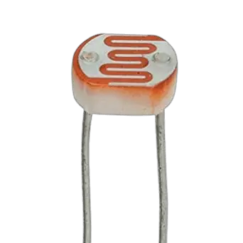
If you need to detect the presence (or absence) of light then use LDR or Photoresistors (or PhotoCells) in your projects The intensity of light causes the resistance to vary which could be from zero to mega ohms in values.
Semiconductor materials that have high light sensitivity properties are used in creating this component. Semiconductors tend to exhibit high resistance by default. The number of electrons is few but when the semiconductor materials receive light photons then it triggers the electrons to break free causing conductivity.
These components are widely available and are easy to use in microcontroller projects.
A note about ADC
The output of an LDR or a photoresistor is an analog signal and for MicroController to understand its value then an Analog to Digital Converter (ADC) is needed. The majority of the popular microcontrollers have pins that have a built-in ADC so reading this component does not need to be complicated.
Components/Parts Required
The followings are the components or parts required to follow along with this post.
- LDR or Photoresistor – Amazon | AliExpress
- ESP32 module (I used 38Pin NodeMCU ESP32S board here) – Amazon | AliExpress | Bangood
- Breadboard – Amazon | AliExpress | Bangood
- Connecting wires – Amazon | AliExpress | Bangood
Disclosure: These are affiliate links and I will earn small commissions to support my site when you buy through these links.
IDE/Software
I used Visual Studio Code with the PlatformIO extension installed in developing this project. If you are in Windows and have not yet installed Visual Studio Code then you can check my post about how to Install Visual Studio Code or VSCode in Windows. If you are not familiar with PlatformIO then please read this PlatformIO Tutorial for Arduino Development where I detailed how to get started with development using the PlatformIO IDE extension
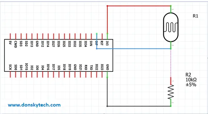
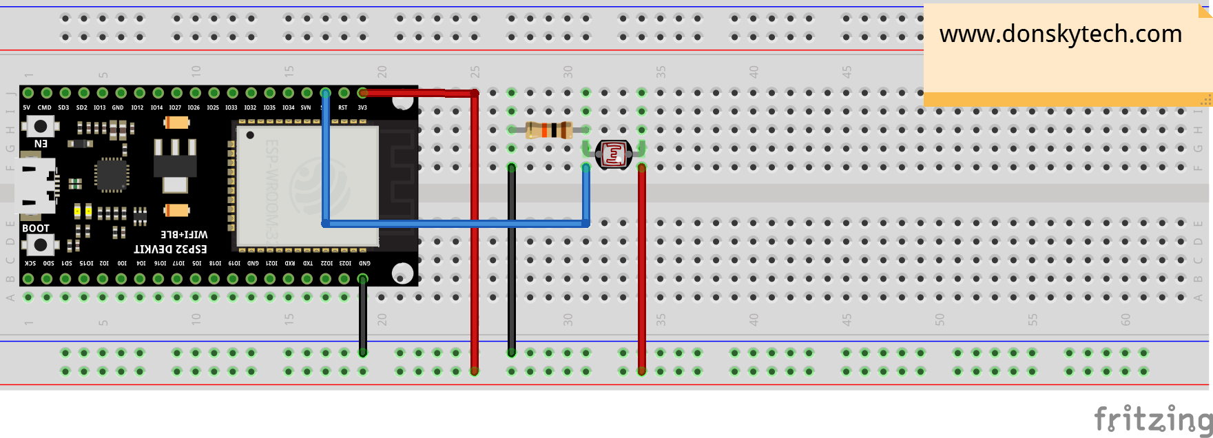
Schematic/Wiring Diagram – ESP32 with LDR/Photoresistor
The following image below is the schematic diagram of our circuit. The Photoresistor/LDR is in series with a resistor to create a voltage divider circuit. The resistance of the Photoresistor/LDR varies depending on the intensity of the light. The GPIO36 pin of the ESP32 reads the amount of voltage drop. Note that the resistance of the Photoresistor/LDR is inversely proportional to the intensity of light captured by the sensor.
Note on choosing GPIO Pins on ESP32 when using WIFI
The ESP32 has 2 ADC (Analog To Digital Converters) namely ADC1 and ADC2 pins that control several GPIO pins under it. If your project will use WIFI functionality along with analogRead then only use pins under ADC1. The ADC2 pins are used internally by ESP32 modules for wifi functionality so you might encounter undesired read results.
Code
#include <Arduino.h>

int sensorVal;
const int ANALOG_READ_PIN = 36; // or A0
const int RESOLUTION = 12; // Could be 9-12

void setup()
{
  Serial.begin(9600);
  delay(1000);
}

void loop()
{
  analogReadResolution(RESOLUTION);
  //Read and print the sensor pin value
  sensorVal = analogRead(ANALOG_READ_PIN);
  Serial.print(sensorVal);
  Serial.print(" \n");
  //sleep for some time before next read
  delay(100);
}
The code for this project is in my GitHub account and you can view it here.
The loop() function contains much of the logic in reading the sensor reads of the LDR/Photoresistor. The analogReadResolution() function will configure the values of the sensor reads and has a default value of 12.
The function analogRead() is what the ESP32 is using to read the Photoresistor or LDR sensor read. It then outputs the value to our serial monitor.
That’s it!
Happy Exploring!
Related Content:
ESP32 Robot Car Using Websockets
Creating an ESP32 RFID with a Web Server Application
Leave a Reply