Introduction
Serial communication is the process of sending messages between a sender and a receiver one bit at a time. Most of the commercially available microcontroller supports this protocol out of the box. In this post, I am going to share with you how you could take advantage of this protocol to control your Arduino projects by using the messages through the serial communication interface. We are going to control our electronic components attached to an Arduino Uno board with messages coming from our laptop (or desktop) computer.
If you want to see a demo of this project in actual video format then please see the video below or watch it on my YouTube channel.
What is Serial Communication?
Before we go deep dive into the project itself, let us pause for a moment and understand what Serial Communication is.
From the Wikipedia article:
Wikipedia:
In telecommunication and data transmission, serial communication is the process of sending data one bit at a time, sequentially, over a communication channel or computer bus. This is in contrast to parallel communication, where several bits are sent as a whole, on a link with several parallel channels.
This article from https://instrumentationblog.com/what-is-serial-communication/ explains the subject of serial communication with visual elements to better understand it.
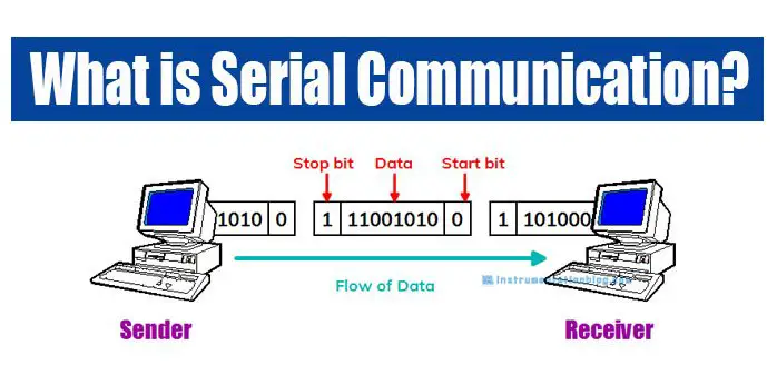
As you can see from the image above, a sender sends a series of bits one at a time to an intended receiver. Messages are structured such as having a Start Bit – Data – Stop Bit for easier decoding of messages. The speed at which the data flows is called the Baud Rate. You will see this information later in the program when we discuss the Python GUI application using PySerial.
In this post, I am using my laptop as the sender with my Arduino Uno microcontroller board as the intended receiver.
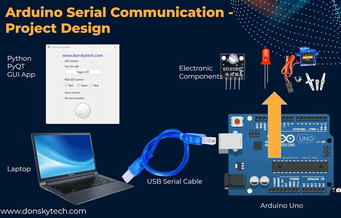
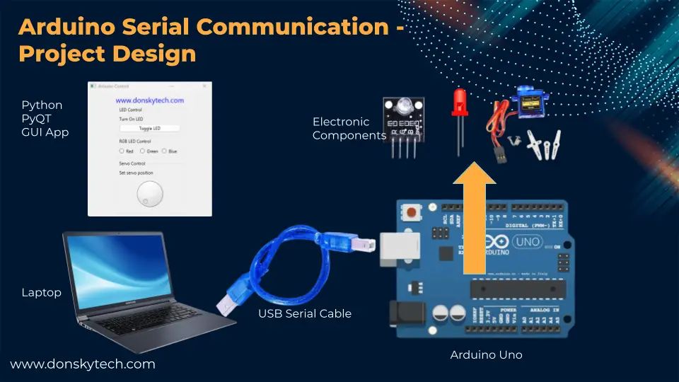
Project Design
The below image shows how we can control our electronic components such as an RGB LED, a normal LED, and a Servo Motor connected to our Arduino Uno through serial communication.
I have created a Python desktop GUI application using the PyQT and sending messages to my Arduino project using the serial communication port interface. I am using the PySerial library to help me communicate with my Arduino Uno.
The Arduino project runs in a continuous loop while waiting for serial messages coming from my Python GUI Application. It then parses the messages received and updates the values of the different electronic components connected to it.
Prerequisites
You should be familiar with Python and know how to draw GUI using the PyQT library. If you want a quick start on the basics of PyQT then you can refer to this GUI Programming With PyQt (Learning Path) – Real Python.
Also, familiarity with Visual Studio Code is important as I have used this IDE in developing this project. The project I built here should work on both Linux and MacOS with some modifications of the commands.
I have also used PlatformIO in developing the Arduino part of this program but you can still use the Arduino IDE if you want.
Related Tutorial:
PlatformIO Tutorial for Arduino Development
Install Visual Studio Code or VSCode on Windows
Parts/Components Required
The following are the components required to follow along with this project.
- Windows 11 Laptop – Amazon | AliExpress
- Arduino Uno R3 – Amazon | AliExpress
- or Arduino Uno R4 – Amazon | AliExpress
- RGB LED Module – Amazon | AliExpress
- SG90 Servo – Amazon | AliExpress
- or MG90 – Amazon | AliExpress
- LED – Amazon | AliExpress
- Resistors (220 Ohms) – Amazon | AliExpress
- Breadboard – Amazon | AliExpress
- Connecting Wires – Amazon | AliExpress
Disclosure: These are affiliate links and I will earn small commissions to support my site when you buy through these links.
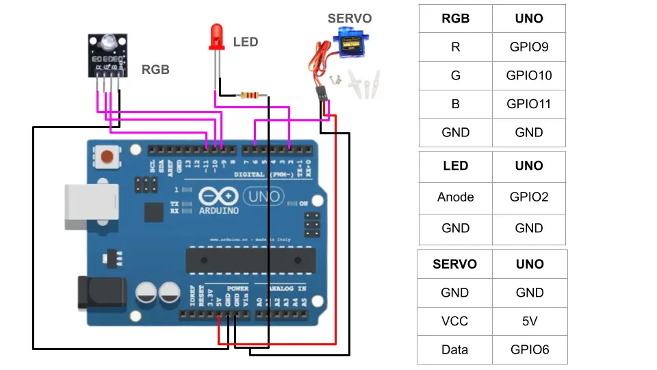
Wiring/Schematic
The below image shows the wiring and schematic that you could follow if you want to recreate this project. Just put a 220-ohm current limiting resistor to your LED to prevent it from burning out.
Code
The complete programs for us to control our Arduino projects through Serial Communication are available on my GitHub account and are subdivided into two projects. First, the Python project is where we draw the graphical user interface for our project using PyQT and send the commands through our Serial Communication. Next, is our Arduino program which will receive the Serial messages and control the attached components.
Python GUI App
You can download the Python project from my GitHub repository using Git or download it as a zip file. If you are using Git then execute the following command to create a local copy of this project and open it in Visual Studio Code.
git clone https://github.com/donskytech/python-pyserial-control.git
cd python-pyserial-control
code .
Or you can download the folder directly by following this How to download a GitHub file, folder, or project?
Once the project is opened in VSCode then open an instance of Terminal by going to the menu Terminal -> New Terminal.
Open a Command Prompt or a Bash Terminal (Linux/Mac) and create a Python Virtual Environment for our project by executing the below commands.
python -m venv .venvNext, activate the virtual environment .venv that we have just created.
# Windows
.venv\Scripts\activate
# Linux/Mac
source .venv/bin/activate
Install the libraries and dependencies by executing the below command.
pip install -r requirements.txt
This project contains only one file which is the serial_control_components.py and it contains the logic for us to control our Arduino projects by sending messages through Serial Communication.
As mentioned above, this Python project uses PyQT6 to create the GUI and the PySerial libraries for sending messages to our Arduino project.
I have structured the program to use the Model-View-Controller(MVC) pattern so that the structure of our program is easier to read. If you are not familiar with MVC then please see the following The ModelView Architecture using PyQT.
A quick visual representation of MVC is described by the following image courtesy of freecodecamp.com

Now so much for theory and let us take a look at the code.
import sys
from PyQt6.QtCore import Qt
from PyQt6.QtWidgets import (
QApplication,
QMainWindow,
QPushButton,
QVBoxLayout,
QWidget,
QLabel,
QDial,
QGroupBox,
QRadioButton,
QButtonGroup,
QHBoxLayout
)
import serial
import time
WINDOW_SIZE = 350
DISPLAY_HEIGHT = 35
BUTTON_SIZE = 40
ERROR_MSG = "ERROR"
class ArduinoModel:
"""Model class representing the Arduino-related data and logic."""
def __init__(self):
self.led_state = False # Initial state: LED is off
self.rgb_led_color = None # Initial state: RGB LED color is not selected
self.servo_position = 0 # Initial state: Servo position is 0
def toggle_led(self):
self.led_state = not self.led_state
def set_rgb_led_color(self, color):
self.rgb_led_color = color
def set_servo_position(self, position):
self.servo_position = position
def get_led_status(self):
return self.led_state
class ArduinoController:
"""Controller class handling user input and updating the model."""
def __init__(self, model):
self.model = model
self.serial_connection = serial.Serial('COM3', 9600)
def handle_led_button_click(self):
self.model.toggle_led()
led_data = f"LED-{self.model.get_led_status()}\n"
print(f"Toggle LED, message : {led_data}")
self.send_serial_message(led_data)
def handle_rgb_led_color_change(self, color):
print(f"RGB LED Color : {color}")
self.model.set_rgb_led_color(color)
# Red = 1, Green = 2, Blue = 3
color_data = None
if (color == "Red"):
color_data = f"RGB-1\n"
elif(color == "Green"):
color_data = f"RGB-2\n"
else:
color_data = f"RGB-3\n"
print(f"Sending serial command : {color_data}")
self.send_serial_message(color_data)
def handle_servo_position_change(self, position):
servo_data = f"SERVO-{position}\n"
self.model.set_servo_position(position)
print(f"Servo Position : {servo_data}")
self.send_serial_message(servo_data)
time.sleep(0.3)
def send_serial_message(self, message):
self.serial_connection.write(message.encode())
class PyControllerWindow(QMainWindow):
"""View class representing the user interface."""
def __init__(self, controller):
super().__init__()
self.setWindowTitle("Arduino Control")
self.setFixedSize(WINDOW_SIZE, WINDOW_SIZE)
self.layout = QVBoxLayout()
self.layout.setAlignment(Qt.AlignmentFlag.AlignHCenter | Qt.AlignmentFlag.AlignTop)
self.centralWidget = QWidget()
self.centralWidget.setLayout(self.layout)
self.setCentralWidget(self.centralWidget)
self.controller = controller
self._create_ui_display()
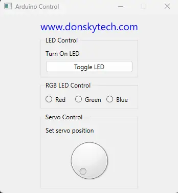
def _create_ui_display(self):
site_label = QLabel("www.donskytech.com")
site_label.setAlignment(Qt.AlignmentFlag.AlignHCenter)
site_label.setStyleSheet("font-size: 20px; color: blue;")
self.layout.addWidget(site_label)
# Group Box for LED-related widgets
led_group = QGroupBox("LED Control")
led_layout = QVBoxLayout()
led_label = QLabel("Turn On LED")
led_button = QPushButton("Toggle LED")
led_button.clicked.connect(self.controller.handle_led_button_click)
led_layout.addWidget(led_label)
led_layout.addWidget(led_button)
led_group.setLayout(led_layout)
self.layout.addWidget(led_group)
# Create a button group for RGB LED
radio_group = QGroupBox("RGB LED Control")
radio_layout = QHBoxLayout()
red = QRadioButton("Red", self)
green = QRadioButton("Green", self)
blue = QRadioButton("Blue", self)
rgb_button_group = QButtonGroup(self)
rgb_button_group.addButton(red)
rgb_button_group.addButton(green)
rgb_button_group.addButton(blue)
rgb_button_group.buttonClicked.connect(self.handle_rgb_led_color_change)
radio_layout.addWidget(red)
radio_layout.addWidget(green)
radio_layout.addWidget(blue)
radio_group.setLayout(radio_layout)
self.layout.addWidget(radio_group)
# Group Box for Servo-related widgets
servo_group = QGroupBox("Servo Control")
servo_layout = QVBoxLayout()
servo_label = QLabel("Set servo position")
servo_dial = QDial()
servo_dial.setMinimum(0)
servo_dial.setMaximum(180)
servo_dial.valueChanged.connect(self.handle_servo_position_change)
servo_layout.addWidget(servo_label)
servo_layout.addWidget(servo_dial)
servo_group.setLayout(servo_layout)
self.layout.addWidget(servo_group)
def handle_rgb_led_color_change(self, button):
color = button.text()
self.controller.handle_rgb_led_color_change(color)
def handle_servo_position_change(self, position):
self.controller.handle_servo_position_change(position)
def main():
model = ArduinoModel()
controller = ArduinoController(model)
controllerApp = QApplication([])
controllerWindow = PyControllerWindow(controller)
controllerWindow.show()
sys.exit(controllerApp.exec())
if __name__ == "__main__":
main()
The above code is the complete code for our Python GUI application. Let us walk through the important parts of the program.
Import the libraries and global variables
import sys
from PyQt6.QtCore import Qt
from PyQt6.QtWidgets import (
    QApplication,
    QMainWindow,
    QPushButton,
    QVBoxLayout,
    QWidget,
    QLabel,
    QDial,
    QGroupBox,
    QRadioButton,
    QButtonGroup,
    QHBoxLayout
)
import serial
import time

WINDOW_SIZE = 350
DISPLAY_HEIGHT = 35
BUTTON_SIZE = 40
ERROR_MSG = "ERROR"
First, we declare all the PyQT widgets that we will be using in this project. Widgets are the user interface that we use to interact with our system such as labels, buttons, radio buttons, or dials.
Also, we import the PySerial library that we will be using to control our Arduino project by sending messages through serial communication. We also set the window size of our GUI and several variables to be used later in the program.
Create the Model class
class ArduinoModel:
    """Model class representing the Arduino-related data and logic."""

    def __init__(self):
        self.led_state = False  # Initial state: LED is off
        self.rgb_led_color = None  # Initial state: RGB LED color is not selected
        self.servo_position = 0  # Initial state: Servo position is 0

    def toggle_led(self):
        self.led_state = not self.led_state

    def set_rgb_led_color(self, color):
        self.rgb_led_color = color

    def set_servo_position(self, position):
        self.servo_position = position

    def get_led_status(self):
        return self.led_state
Our model for this project contains the different values that we wanted to take note such as the LED state, the color of the RGB module, and the current position of the servo motor.
I have defined a class named ArduinoModel to represent these states and it contains methods to set the values that we need to take note of.
Create the Controller Class
class ArduinoController:
    """Controller class handling user input and updating the model."""

    def __init__(self, model):
        self.model = model
        self.serial_connection = serial.Serial('COM3', 9600)

    def handle_led_button_click(self):
        self.model.toggle_led()
        led_data = f"LED-{self.model.get_led_status()}\n"
        print(f"Toggle LED, message : {led_data}")
        self.send_serial_message(led_data)

    def handle_rgb_led_color_change(self, color):
        print(f"RGB LED Color : {color}")
        self.model.set_rgb_led_color(color)
        # Red = 1, Green = 2, Blue = 3
        color_data = None
        if (color == "Red"):
            color_data = f"RGB-1\n"
        elif(color == "Green"):
            color_data = f"RGB-2\n"
        else:
            color_data = f"RGB-3\n"
        print(f"Sending serial command : {color_data}")
        self.send_serial_message(color_data)

    def handle_servo_position_change(self, position):
        servo_data = f"SERVO-{position}\n"
        self.model.set_servo_position(position)
        print(f"Servo Position : {servo_data}")
        self.send_serial_message(servo_data)
        time.sleep(0.3)

    def send_serial_message(self, message):
        self.serial_connection.write(message.encode())
This is the Controller of our GUI project whose main job is to respond to user inputs such as clicking the button, changing the RGB color by selecting different radio buttons, and responding to movement in the dial control.
class ArduinoController:
    """Controller class handling user input and updating the model."""

    def __init__(self, model):
        self.model = model
        self.serial_connection = serial.Serial('COM3', 9600)
The constructor requires the model class and the PySerial connection. Changed this according to the COM port where your Arduino Uno is connected.
    def handle_led_button_click(self):
        self.model.toggle_led()
        led_data = f"LED-{self.model.get_led_status()}\n"
        print(f"Toggle LED, message : {led_data}")
        self.send_serial_message(led_data)

    def handle_rgb_led_color_change(self, color):
        print(f"RGB LED Color : {color}")
        self.model.set_rgb_led_color(color)
        # Red = 1, Green = 2, Blue = 3
        color_data = None
        if (color == "Red"):
            color_data = f"RGB-1\n"
        elif(color == "Green"):
            color_data = f"RGB-2\n"
        else:
            color_data = f"RGB-3\n"
        print(f"Sending serial command : {color_data}")
        self.send_serial_message(color_data)

    def handle_servo_position_change(self, position):
        servo_data = f"SERVO-{position}\n"
        self.model.set_servo_position(position)
        print(f"Servo Position : {servo_data}")
        self.send_serial_message(servo_data)
        time.sleep(0.3)
These methods will update our model classes to take note of the currently selected values from our GUI app. In addition, for each movement, we send messages through the Serial Port by calling the method send_serial_message()
Notice also that I have followed certain conventions in sending the serial messages so that it would be easy to decode in our Arduino project.
- LED-True or LED-False – for toggling the LED status
- RGB-1 for Red, RGB-2 for Green, and RGB-3 for Blue
- Servo – 0 to Servo-180 for servo positions between zero to one hundred eighty degrees.
    def send_serial_message(self, message):
        self.serial_connection.write(message.encode())
The above method is what we used to send messages to our Arduino Uno microcontroller.
Create the View or the GUI of our project
class PyControllerWindow(QMainWindow):
    """View class representing the user interface."""

    def __init__(self, controller):
        super().__init__()
        self.setWindowTitle("Arduino Control")
        self.setFixedSize(WINDOW_SIZE, WINDOW_SIZE)
        self.layout = QVBoxLayout()
        self.layout.setAlignment(Qt.AlignmentFlag.AlignHCenter | Qt.AlignmentFlag.AlignTop)

        self.centralWidget = QWidget()
        self.centralWidget.setLayout(self.layout)
        self.setCentralWidget(self.centralWidget)

        self.controller = controller
        self._create_ui_display()

    def _create_ui_display(self):
        site_label = QLabel("www.donskytech.com")
        site_label.setAlignment(Qt.AlignmentFlag.AlignHCenter)
        site_label.setStyleSheet("font-size: 20px; color: blue;")

        self.layout.addWidget(site_label)

        # Group Box for LED-related widgets
        led_group = QGroupBox("LED Control")
        led_layout = QVBoxLayout()

        led_label = QLabel("Turn On LED")
        led_button = QPushButton("Toggle LED")
        led_button.clicked.connect(self.controller.handle_led_button_click)

        led_layout.addWidget(led_label)
        led_layout.addWidget(led_button)

        led_group.setLayout(led_layout)
        self.layout.addWidget(led_group)

        # Create a button group for RGB LED
        radio_group = QGroupBox("RGB LED Control")
        radio_layout = QHBoxLayout()

        red = QRadioButton("Red", self)
        green = QRadioButton("Green", self)
        blue = QRadioButton("Blue", self)

        rgb_button_group = QButtonGroup(self)
        rgb_button_group.addButton(red)
        rgb_button_group.addButton(green)
        rgb_button_group.addButton(blue)
        rgb_button_group.buttonClicked.connect(self.handle_rgb_led_color_change)

        radio_layout.addWidget(red)
        radio_layout.addWidget(green)
        radio_layout.addWidget(blue)

        radio_group.setLayout(radio_layout)
        self.layout.addWidget(radio_group)

        # Group Box for Servo-related widgets
        servo_group = QGroupBox("Servo Control")
        servo_layout = QVBoxLayout()

        servo_label = QLabel("Set servo position")
        servo_dial = QDial()
        servo_dial.setMinimum(0)
        servo_dial.setMaximum(180)
        servo_dial.valueChanged.connect(self.handle_servo_position_change)

        servo_layout.addWidget(servo_label)
        servo_layout.addWidget(servo_dial)

        servo_group.setLayout(servo_layout)
        self.layout.addWidget(servo_group)

    def handle_rgb_led_color_change(self, button):
        color = button.text()
        self.controller.handle_rgb_led_color_change(color)

    def handle_servo_position_change(self, position):
        self.controller.handle_servo_position_change(position)
The above code represents our GUI object and uses different PyQT widgets and layout managers to properly draw the user interface.
class PyControllerWindow(QMainWindow):
    """View class representing the user interface."""

    def __init__(self, controller):
        super().__init__()
        self.setWindowTitle("Arduino Control")
        self.setFixedSize(WINDOW_SIZE, WINDOW_SIZE)
        self.layout = QVBoxLayout()
        self.layout.setAlignment(Qt.AlignmentFlag.AlignHCenter | Qt.AlignmentFlag.AlignTop)

        self.centralWidget = QWidget()
        self.centralWidget.setLayout(self.layout)
        self.setCentralWidget(self.centralWidget)

        self.controller = controller
        self._create_ui_display()
In the class constructor, we supplied it with a reference to our controller. After that, we set the size of the window and began constructing the layout of our main widget. The last part is where we call the method self._create_ui_display() where the actual drawing of the user interface is done.
    def _create_ui_display(self):
        site_label = QLabel("www.donskytech.com")
        site_label.setAlignment(Qt.AlignmentFlag.AlignHCenter)
        site_label.setStyleSheet("font-size: 20px; color: blue;")

        self.layout.addWidget(site_label)

        # Group Box for LED-related widgets
        led_group = QGroupBox("LED Control")
        led_layout = QVBoxLayout()

        led_label = QLabel("Turn On LED")
        led_button = QPushButton("Toggle LED")
        led_button.clicked.connect(self.controller.handle_led_button_click)

        led_layout.addWidget(led_label)
        led_layout.addWidget(led_button)

        led_group.setLayout(led_layout)
        self.layout.addWidget(led_group)

        # Create a button group for RGB LED
        radio_group = QGroupBox("RGB LED Control")
        radio_layout = QHBoxLayout()

        red = QRadioButton("Red", self)
        green = QRadioButton("Green", self)
        blue = QRadioButton("Blue", self)

        rgb_button_group = QButtonGroup(self)
        rgb_button_group.addButton(red)
        rgb_button_group.addButton(green)
        rgb_button_group.addButton(blue)
        rgb_button_group.buttonClicked.connect(self.handle_rgb_led_color_change)

        radio_layout.addWidget(red)
        radio_layout.addWidget(green)
        radio_layout.addWidget(blue)

        radio_group.setLayout(radio_layout)
        self.layout.addWidget(radio_group)

        # Group Box for Servo-related widgets
        servo_group = QGroupBox("Servo Control")
        servo_layout = QVBoxLayout()

        servo_label = QLabel("Set servo position")
        servo_dial = QDial()
        servo_dial.setMinimum(0)
        servo_dial.setMaximum(180)
        servo_dial.valueChanged.connect(self.handle_servo_position_change)

        servo_layout.addWidget(servo_label)
        servo_layout.addWidget(servo_dial)

        servo_group.setLayout(servo_layout)
        self.layout.addWidget(servo_group)
This part of the program is where we create the different widgets that we use to control our Arduino project. It uses standard PyQT layout managers and widget components such as buttons, radio buttons, and dials. We also attached several event handlers to respond to the user clicking the button, changing the color of the RGB LED module, or adjusting the dial range.
    def handle_rgb_led_color_change(self, button):
        color = button.text()
        self.controller.handle_rgb_led_color_change(color)

    def handle_servo_position_change(self, position):
        self.controller.handle_servo_position_change(position)
These are the event handlers that get called when the user interacts with our user interface. It delegates the process of handling user events to our Controller class so that we can update our Model.
Running the GUI Application
def main():
    model = ArduinoModel()
    controller = ArduinoController(model)
    controllerApp = QApplication([])
    controllerWindow = PyControllerWindow(controller)
    controllerWindow.show()
    sys.exit(controllerApp.exec())

if __name__ == "__main__":
    main()
The function main() is where we initialize all the parts of our MVC. We instantiated a PyQT Application and passed in our Model, View, and Controller classes.
To run the application and see the result, just open another terminal and execute the following command. This should run the Python GUI application that will allow us to send messages to our Arduino project through the Serial Communication interface.
python serial_control_components.pyNow that we have discussed the Python GUI application then we can go over how to react to the messages sent through the serial port interface in our Arduino project.
Arduino Application
The Arduino project code that would receive serial communication messages can be found here. You can download this folder by following this How to download a GitHub file, folder, or project?
Open the project in Visual Studio Code and PlatformIO IDE. Below is the complete code for our Arduino project.
#include <Arduino.h>
#include <Servo.h>

const int BUFFER_SIZE = 256;
char receivedMessage[BUFFER_SIZE];
bool messageComplete = false;

// LED PIN Setup
int ledStatus = LOW;
const int LED_PIN = 2;

// RGB LED PIN Setup
const int redPin = 9;
const int greenPin = 10;
const int bluePin = 11;
int currentColor = 0;

// Servo PinSetup
int servoPin = 6;
Servo servoMotor;
int currentServoPosition = 0;

//  Forward Declaration
void processMessage(const char *message);
void setColor(int red, int green, int blue);
void moveServo(int position);

void setup()
{
  Serial.begin(9600);
  Serial.setTimeout(1000); // Set a timeout for Serial.readBytesUntil
  // Initialize other setup tasks if needed
  pinMode(LED_PIN, OUTPUT);
  // RGB LED
  pinMode(redPin, OUTPUT);
  pinMode(greenPin, OUTPUT);
  pinMode(bluePin, OUTPUT);

  servoMotor.attach(servoPin, 550, 2650);
  moveServo(0);
}

void loop()
{
  if (Serial.available() > 0 && !messageComplete)
  {
    // Read the incoming characters until newline character is received
    int bytesRead = Serial.readBytesUntil('\n', receivedMessage, BUFFER_SIZE - 1);

    if (bytesRead > 0)
    {
      receivedMessage[bytesRead] = '\0';
      Serial.print("Received message: ");
      Serial.println(receivedMessage);

      // Process received message
      processMessage(receivedMessage);

      // Reset the buffer and flag for the next message
      memset(receivedMessage, 0, sizeof(receivedMessage));
      messageComplete = true;
    }
  }

  // Reset the messageComplete flag after performing tasks
  if (messageComplete)
  {
    messageComplete = false;
    digitalWrite(LED_PIN, ledStatus);

    if (currentColor == 1)
    {
      setColor(255, 0, 0);
    }
    else if (currentColor == 2)
    {
      setColor(0, 255, 0);
    }
    else if (currentColor == 3)
    {
      setColor(0, 0, 255);
    }
    moveServo(currentServoPosition);
    delay(100);
  }
}

void processMessage(const char *message)
{
  // Check if the message starts with "RGB"
  if (strncmp(message, "RGB-", 4) == 0)
  {
    // Process RGB command
    currentColor = atoi(message + 4); // Extract color value after "RGB-"
  }
  // Check if the message starts with "LED"
  else if (strncmp(message, "LED-", 4) == 0)
  {
    // Process LED command
    bool ledState = atoi(message + 4); // Extract LED state after "LED-"
  }
  // Check if the message starts with "SERVO"
  else if (strncmp(message, "SERVO-", 6) == 0)
  {
    // Process SERVO command
    int servoPosition = atoi(message + 6); // Extract servo position after "SERVO-"
    currentServoPosition = servoPosition;
  }
  // Unknown command
  else
  {
    Serial.println("Unknown command");
  }
}

void setColor(int red, int green, int blue)
{
  analogWrite(redPin, red);
  analogWrite(greenPin, green);
  analogWrite(bluePin, blue);
}

void moveServo(int position)
{
  // Set the servo position
  servoMotor.write(position);

  // Wait for some time
  delay(15);
}
Let us go over what each line of the code does.
#include <Arduino.h>
#include <Servo.h>

const int BUFFER_SIZE = 256;
char receivedMessage[BUFFER_SIZE];
bool messageComplete = false;

// LED PIN Setup
int ledStatus = LOW;
const int LED_PIN = 2;

// RGB LED PIN Setup
const int redPin = 9;
const int greenPin = 10;
const int bluePin = 11;
int currentColor = 0;

// Servo PinSetup
int servoPin = 6;
Servo servoMotor;
int currentServoPosition = 0;
First, we import the Arduino and Servo libraries. Next, we defined several global variables to handle the Serial messages sent by our Python GUI application through serial communication. Lastly, we defined the pins where we have connected our LED, RGB LED, and Servo motor.
//  Forward Declaration
void processMessage(const char *message);
void setColor(int red, int green, int blue);
void moveServo(int position);

void setup()
{
  Serial.begin(9600);
  Serial.setTimeout(1000); // Set a timeout for Serial.readBytesUntil
  // Initialize other setup tasks if needed
  pinMode(LED_PIN, OUTPUT);
  // RGB LED
  pinMode(redPin, OUTPUT);
  pinMode(greenPin, OUTPUT);
  pinMode(bluePin, OUTPUT);

  servoMotor.attach(servoPin, 550, 2650);
  moveServo(0);
}
We forward declared several functions that we will be using later in the program. In the setup() function, we initialized our serial monitor and the pins where we connected our components to our Arduino Uno board.
Finally, we initialized the servo to move to its default zero-degree position.
void loop()
{
  if (Serial.available() > 0 && !messageComplete)
  {
    // Read the incoming characters until newline character is received
    int bytesRead = Serial.readBytesUntil('\n', receivedMessage, BUFFER_SIZE - 1);

    if (bytesRead > 0)
    {
      receivedMessage[bytesRead] = '\0';
      Serial.print("Received message: ");
      Serial.println(receivedMessage);

      // Process received message
      processMessage(receivedMessage);

      // Reset the buffer and flag for the next message
      memset(receivedMessage, 0, sizeof(receivedMessage));
      messageComplete = true;
    }
  }

  // Reset the messageComplete flag after performing tasks
  if (messageComplete)
  {
    messageComplete = false;
    digitalWrite(LED_PIN, ledStatus);

    if (currentColor == 1)
    {
      setColor(255, 0, 0);
    }
    else if (currentColor == 2)
    {
      setColor(0, 255, 0);
    }
    else if (currentColor == 3)
    {
      setColor(0, 0, 255);
    }
    moveServo(currentServoPosition);
    delay(100);
  }
}
The function loop() is where we continuously wait for messages coming from our serial communication port interface.
As mentioned above we parsed the whole Serial Messages and extracted the values by passing them to our function processMessage().
Once the message is completely received then we could set the values of our global variables and turn on or turn off the LED, set the RGB color, and move the servo position.
void processMessage(const char *message)
{
  // Check if the message starts with "RGB"
  if (strncmp(message, "RGB-", 4) == 0)
  {
    // Process RGB command
    currentColor = atoi(message + 4); // Extract color value after "RGB-"
  }
  // Check if the message starts with "LED"
  else if (strncmp(message, "LED-", 4) == 0)
  {
    // Process LED command
    bool ledState = atoi(message + 4); // Extract LED state after "LED-"
  }
  // Check if the message starts with "SERVO"
  else if (strncmp(message, "SERVO-", 6) == 0)
  {
    // Process SERVO command
    int servoPosition = atoi(message + 6); // Extract servo position after "SERVO-"
    currentServoPosition = servoPosition;
  }
  // Unknown command
  else
  {
    Serial.println("Unknown command");
  }
}
In this function, we compare the start of the Serial messages sent by the Python GUI Application and extract the values accordingly. So if we receive a serial message that starts with “RGB” then we assign it to the currentColor global variable. Same also with the “LED” and “SERVO” messages.
void setColor(int red, int green, int blue)
{
  analogWrite(redPin, red);
  analogWrite(greenPin, green);
  analogWrite(bluePin, blue);
}

void moveServo(int position)
{
  // Set the servo position
  servoMotor.write(position);

  // Wait for some time
  delay(15);
}
These are functions that instruct the Arduino to change the RGB LED module color and move the servo to the desired position.
That is all there is for the code.
How to run the two applications?
The following are the steps that I followed so that I could run and test the application.
- Plugin your Arduino Uno microcontroller and take note of the COM port where it was assigned by your Windows system.
- Open the Arduino project and upload the project to your Microcontroller
- Disconnect the cable temporarily and reconnect it.
- Next, open the Python GUI application and set the COM port that was assigned by your system.
- Run the Python GUI Application and try to toggle the button, choose the RGB LED color, or move the dial. Verify if the components attached to your microcontroller have changed or moved.
Wrap Up
In this post, I have shown you how you could take advantage of the serial communication port to send and receive messages between your laptop and an Arduino circuit. I have shown you how easy it is to create a visual GUI interface to control your circuit.
So what exciting project are you planning to do next? I hope you learned something. Happy exploring!
Read Next:
Using ESP32 SoftwareSerial in your Arduino Projects
Arduino Data Logger using MongoDB Database
Leave a Reply