- Introduction
- What is the PCF8575?
- Parts/Components Required
- Prerequisites
- Scan the I2C Address of your PCF8575
- Help! PCF8575 always changes its I2C address when I ran the I2C scanner
- PCF8575 Port Expander Library
- Wiring/Schematic
- Blink LED using PCF8575 Port Expander
- Button using PCF8575 Port Expander
- Control Relay using PCF8575 Port Expander
- PCF8575 Issues
- Wrap up
Introduction
The ESP32 microcontroller in itself contains multiple pins that can drive an assortment of sensors and devices. However, many Internet of Things (IoT) projects may require more pins, and the ESP32 only has a finite number of GPIO(General Purpose Input Output) pins. The PCF8575 GPIO port expander comes into the picture as you can add more GPIO pins by just using two pins from your ESP32. This post will show you how you can add or expand the number of GPIO pins of your ESP32 running the Arduino framework.
If you want to see a video demo of the project in this post then please see below or watch it on my YouTube channel.
What is the PCF8575?
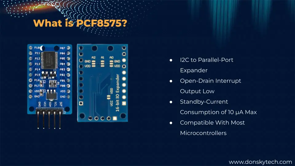
The PCF8575 device provides general-purpose remote I/O expansion for most microcontroller families by way of the I2C interface [serial clock (SCL), serial data (SDA)].
Texas Instrument Datasheet
The PCF8575 often comes in both IC and module form but I highly suggest you use the module design as it already contains the pull-up resistors and protection circuits already.
I often hear questions like:
- How do I add more GPIO ports to my microcontroller?
- How can I increase my GPIO ports as I need to control multiple sensors or devices?
- I run out of GPIO pins for my ESP32, how can I expand it further?
This is what the I/O expansion board solves as modules such as the PCF8575 add more GPIO pins to the existing pins of your ESP32 by way of using the I2C interface.
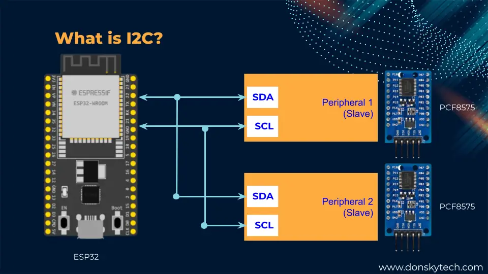
I2C or Inter-Integrated Circuit (pronounced as eye-squared C) is one of the popular communication protocols used to allow multiple sensors to communicate with your microcontrollers. I2C uses two wires which are called the SCL (Serial Clock) and SDA (Serial Data). Well, technically speaking it is still 4 wires as you need the GND and VCC pins to provide power. It can support multiple controllers(masters) and multiple devices or peripherals(slaves ). This ability to connect multiple sensors on a single bus (SDA/SCL combination) makes it ideal for any Arduino-powered circuits especially if you are controlling multiple sensors or components.
PCF8575 Cons/Drawbacks
The PCF8575 looks powerful but does it have any drawbacks or cons? Well, if your electronic circuit requires precise or immediate response then using this module could add a little delay as the signals are still passing thru the SDA and SCL pins in synchronous mode.
PCF8575 sample projects
Now so much for theory, if you want to know more about this IC or module then you could read the datasheets further.
In this post, we will try to use this component to do the following use cases:
- Blink an LED or multiple LEDs if you wanted to create your own light show project
- Get the button pin status like if you are using a keypad
- Drive high-power/high-current devices using a Relay
Parts/Components Required
The following components are required to follow along with this post.
- ESP32 (I used NodeMCU ESP32) – Amazon | AliExpress | Bangood
- PCF8575 Port Expander – Amazon | AliExpress
- LED – Amazon | AliExpress | Bangood
- Button Switch – Amazon | AliExpress
- Resistors (220 Ohms and 10K Ohms) – Amazon | AliExpress | Bangood
- 16 Channel Relay – Amazon | AliExpress
- Bench Power Supply – Amazon | AliExpress | Bangood
- Breadboard – Amazon | AliExpress | Bangood
- Connecting Wires – Amazon | AliExpress | Bangood
Disclosure: These are affiliate links and I will earn small commissions to support my site when you buy through these links.
Prerequisites
I am using Visual Studio Code with PlatformIO IDE extension installed in this post but you can also use the Arduino IDE if you want.
Related Content:
PlatformIO Tutorial for Arduino Development
Scan the I2C Address of your PCF8575
I cannot emphasize this enough but whenever you are working with an I2C device then the very first thing to do is to check the address assigned to it. We cannot have two I2C devices on the same I2C bus thus it is important to know the I2C address of your PCF8575 using the below code.
 // This gist was copied from the Arduino site and place here just for reference

// --------------------------------------
// i2c_scanner
//
// Version 1
//    This program (or code that looks like it)
//    can be found in many places.
//    For example on the Arduino.cc forum.
//    The original author is not know.
// Version 2, Juni 2012, Using Arduino 1.0.1
//     Adapted to be as simple as possible by Arduino.cc user Krodal
// Version 3, Feb 26  2013
//    V3 by louarnold
// Version 4, March 3, 2013, Using Arduino 1.0.3
//    by Arduino.cc user Krodal.
//    Changes by louarnold removed.
//    Scanning addresses changed from 0...127 to 1...119,
//    according to the i2c scanner by Nick Gammon
//    https://www.gammon.com.au/forum/?id=10896
// Version 5, March 28, 2013
//    As version 4, but address scans now to 127.
//    A sensor seems to use address 120.
// Version 6, November 27, 2015.
//    Added waiting for the Leonardo serial communication.
//
//
// This sketch tests the standard 7-bit addresses
// Devices with higher bit address might not be seen properly.
//

#include <Wire.h>


void setup()
{
  Wire.begin();

  Serial.begin(9600);
  while (!Serial);             // Leonardo: wait for serial monitor
  Serial.println("\nI2C Scanner");
}


void loop()
{
  byte error, address;
  int nDevices;

  Serial.println("Scanning...");

  nDevices = 0;
  for(address = 1; address < 127; address++ )
  {
    // The i2c_scanner uses the return value of
    // the Write.endTransmisstion to see if
    // a device did acknowledge to the address.
    Wire.beginTransmission(address);
    error = Wire.endTransmission();

    if (error == 0)
    {
      Serial.print("I2C device found at address 0x");
      if (address<16)
        Serial.print("0");
      Serial.print(address,HEX);
      Serial.println("  !");

      nDevices++;
    }
    else if (error==4)
    {
      Serial.print("Unknown error at address 0x");
      if (address<16)
        Serial.print("0");
      Serial.println(address,HEX);
    }
  }
  if (nDevices == 0)
    Serial.println("No I2C devices found\n");
  else
    Serial.println("done\n");

  delay(5000);           // wait 5 seconds for next scan
}
Your terminal should print the following information. In my case, the I2C address of my PCF8575 is 0x20.
Scanning...
I2C device found at address 0x20  !
done
Related Content:
How to use the Arduino I2C Scanner?
Help! PCF8575 always changes its I2C address when I ran the I2C scanner
One issue that I have encountered when working with the module type of the PCF8575 is that when I ran the Arduino I2C scanner, is that it prints out a different I2C address. The reason is that the A0, A1, and A2 pin is left in a floating state. To fix the issue, make sure that you solder the pad at the back of the module.
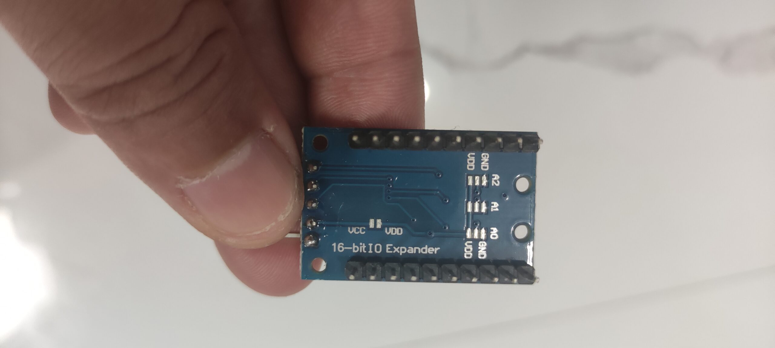
Notice the middle pad is sandwiched between a GND and VDD values so if you want to set the I2C address manually then solder it to either the GND or VDD pad.
Attaching all middle pads to GND would force the PCF8575 address to be in 0 otherwise it will be 1.
PCF8575 I2C Addressing
Please see the below table for your reference when you try to set the i2C address of your PCF8575
| A0 | A1 | A2 | Result |
| 0 | 0 | 0 | 0x20 |
| 0 | 0 | 1 | 0x21 |
| 0 | 1 | 0 | 0x22 |
| 0 | 1 | 1 | 0x23 |
| 1 | 0 | 0 | 0x24 |
| 1 | 0 | 1 | 0x25 |
| 1 | 1 | 0 | 0x26 |
| 1 | 1 | 1 | 0x27 |
PCF8575 Port Expander Library
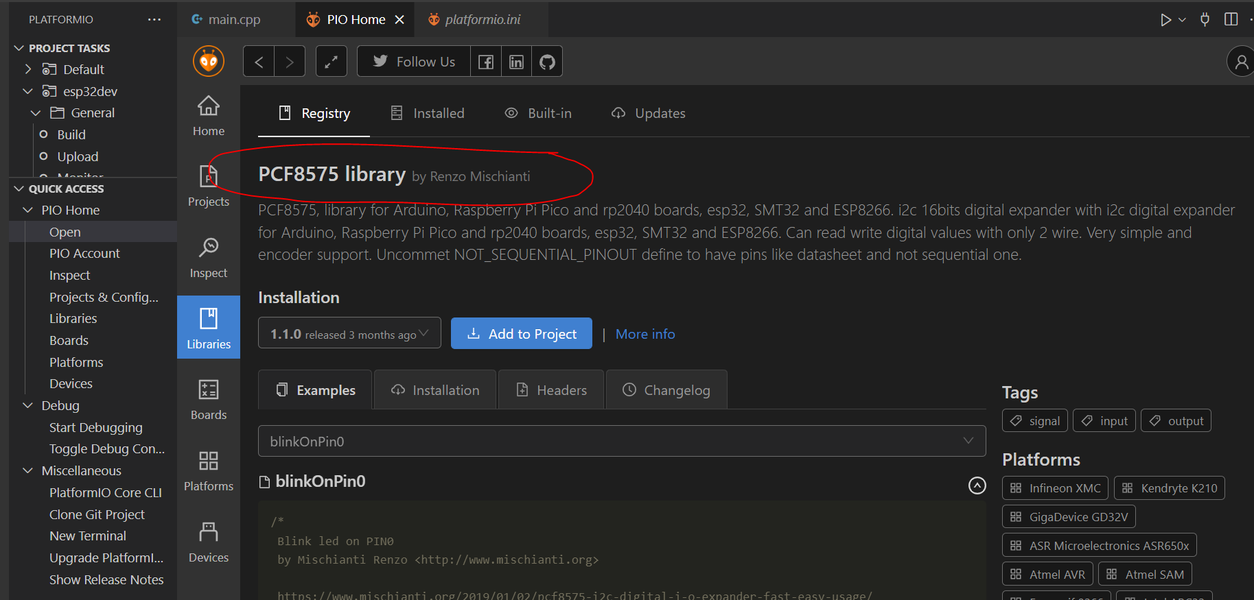
There are lots of Arduino libraries available to drive our PCF8575 Port expander module but I find this library by Renzo Mischianti to be easy to use. So let us try adding the said library to your project.
If you are using the PlatformIO IDE then search for it on the Libraries tab of your PlatformIO home section.
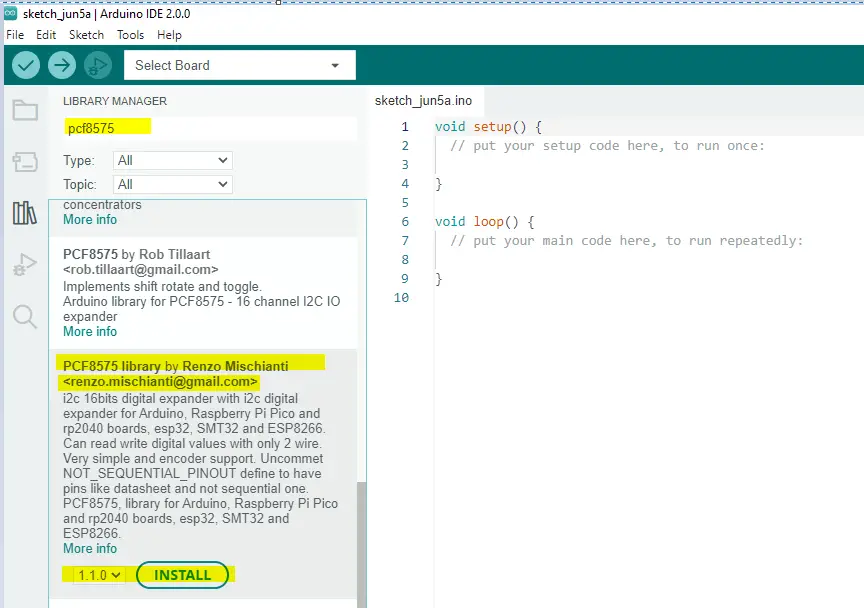
On the other hand, if you are using Arduino IDE 2.0 then add the same library on the tab also.
Wiring/Schematic
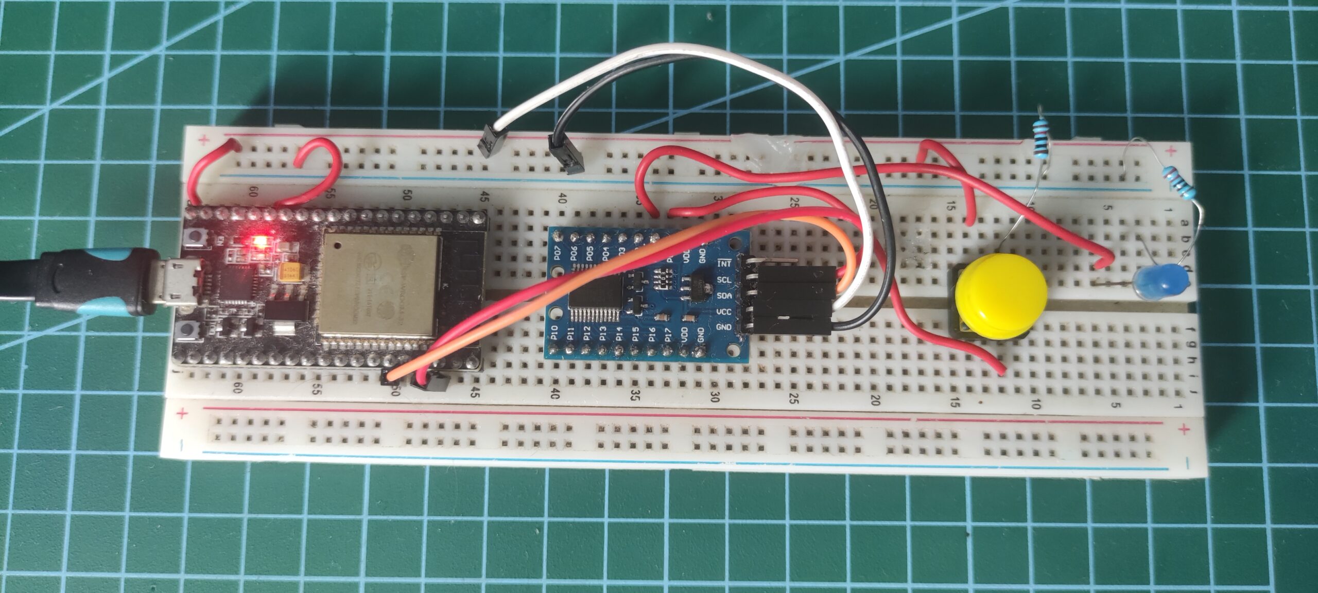
PCF8575 and LED Blink/Button Switch
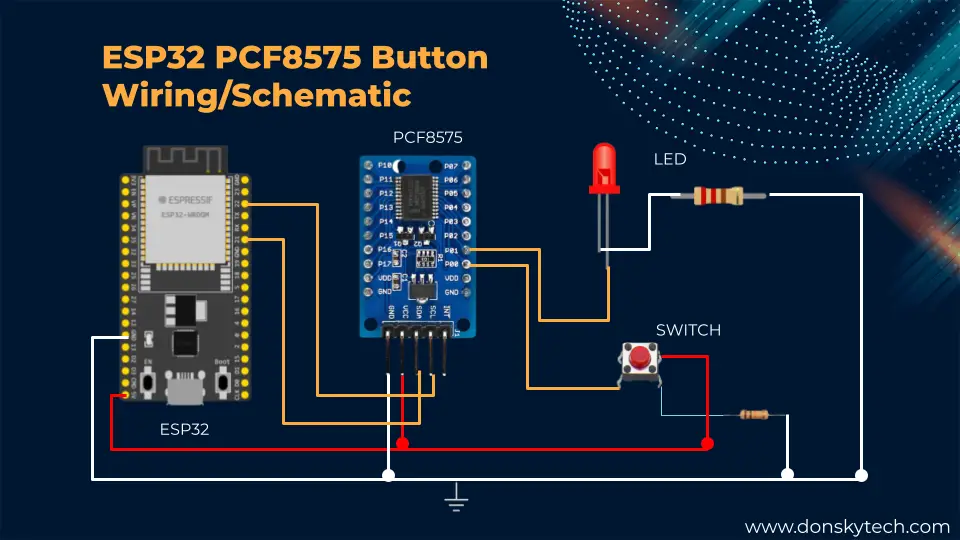
We will use the schematic/wiring above for our ESP32 and PCF8575 LED Blink and Button switch handling project. You can follow the steps below for your reference:
- Connect ESP32 GPIO22 (SCL) to the PCF8575 SCL Pin
- Connect ESP32 GPIO21 (SDA) to the PCF8575 SDA Pin
- Connect ESP32 VIn(5V) to VCC of PCF8575
- Connect ESP32 GND to PCF8575 GND
- Connect the PCF8575 P0 pin to one end of the switch. The other end is connected to 5V of the ESP32. Add a 10K pull-down resistor connected to the ground.
- Connect PCF8575 P1 to the Anode of the LED. Add a 220 Ohm current limiting resistor to the cathode to GND.
PCF8575 and Relay
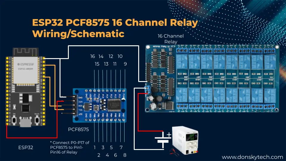
The image above is our schematic/wiring when you plan to use the ESP32 in driving a 16-channel high current load such as motors or AC devices.
- Connect ESP32 GPIO22 (SCL) to the PCF8575 SCL Pin
- Connect ESP32 GPIO21 (SDA) to the PCF8575 SDA Pin
- Connect ESP32 VIn(5V) to VCC of PCF8575
- Connect ESP32 GND to PCF8575 GND
- Connect the DC(+) of the relay to the Positive(+) of your bench power supply.
- Connect the DC(-) of the relay to the Negative(-) of your bench power supply.
- Connect the PF8575 P0-P17 pins to the Pin 1-16 of your 16-Channel relay
Blink LED using PCF8575 Port Expander
#include "Arduino.h"
#include "PCF8575.h"

// Set i2c address
PCF8575 pcf8575(0x20);

void setup()
{
  Serial.begin(9600);

  // Set pinMode to OUTPUT
  pcf8575.pinMode(P1, OUTPUT);
  pcf8575.begin();
}

void loop()
{
  pcf8575.digitalWrite(P1, HIGH);
  delay(1000);
  pcf8575.digitalWrite(P1, LOW);
  delay(1000);
}
The code above is how easy it is to blink an LED using your ESP32 and PCF8575 GPIO port expander.
#include "Arduino.h"
#include "PCF8575.h"
First, we import the necessary Arduino and PCF8575 header files.
// Set i2c address
PCF8575 pcf8575(0x20);
Next, we create an object of PCF8575 Class and passed in the I2C address of your PCF8575.
void setup()
{
  Serial.begin(9600);

  // Set pinMode to OUTPUT
  pcf8575.pinMode(P1, OUTPUT);
  pcf8575.begin();
}
In the function setup(), we just initialize the baud rate of the serial monitor and set the mode to output, and begin the communication.
void loop()
{
  pcf8575.digitalWrite(P1, HIGH);
  delay(1000);
  pcf8575.digitalWrite(P1, LOW);
  delay(1000);
}
Lastly, the function loop() will just toggle the value of your LED.
Button using PCF8575 Port Expander
#include "Arduino.h"
#include "PCF8575.h"

// Set i2c address
PCF8575 pcf8575(0x20);

void setup()
{
  Serial.begin(9600);

  pcf8575.pinMode(P0, INPUT);
  pcf8575.pinMode(P1, OUTPUT);

  pcf8575.begin();
}

void loop()
{
  uint8_t val = pcf8575.digitalRead(P0);
  if (val == HIGH)
  {
    pcf8575.digitalWrite(P1, HIGH);
  }
  else
  {
    pcf8575.digitalWrite(P1, LOW);
  }

  delay(50);
}
If you want to use the PCF8575 to read button inputs such as the Keypad matrix below so you won’t need to connect all of its inputs to the ESP32 then you can use the code above.
#include "Arduino.h"
#include "PCF8575.h"

// Set i2c address
PCF8575 pcf8575(0x20);
Same as the Blink LED code above then we just need to import the header file and create an object of class PCF8575 where we passed in the i2C address that we have set.
void setup()
{
  Serial.begin(9600);

  pcf8575.pinMode(P0, INPUT);
  pcf8575.pinMode(P1, OUTPUT);

  pcf8575.begin();
}
In the function setup(), we initialize both the P0 and P1 pins as INPUT and OUTPUT and begin the communication with PCF8575.
void loop()
{
  uint8_t val = pcf8575.digitalRead(P0);
  if (val == HIGH)
  {
    pcf8575.digitalWrite(P1, HIGH);
  }
  else
  {
    pcf8575.digitalWrite(P1, LOW);
  }

  delay(50);
}
We read the status of our P0 input pins to check if it is pressed or not. If it returns a HIGH signal then it is pressed so we turn on our LED connected to P1. Otherwise, we turn it off.
This is how easy it is to use this library.
Control Relay using PCF8575 Port Expander
/*
  Project Desc: Control 16 Channel relays
  By: DonskyTech (www.donskytech.com)

  WIRING/SCHEMATIC

  RELAY   Power Supply
  DC(+)   Power Supply (+) 5V
  DC(-)   Power Supply (-) 5V

  RELAY   ESP32
  GND     GND
  5v      NO CONNECTION

  PCF8575 RELAY
  P0      IN1
  P1      IN1
  P2      IN3
  .
  .
  .
  P15     IN16
*/

#include "Arduino.h"
#include "PCF8575.h"

// Set i2c address
PCF8575 pcf8575(0x20);

const int INITIAL_PIN_RELAY = 0;
const int RELAY_PIN_COUNT = 16;
void setup()
{
  Serial.begin(9600);

  // Set All Pins to OUTPUT
  for (int iCtr = INITIAL_PIN_RELAY; iCtr < RELAY_PIN_COUNT; iCtr++)
  {
    pcf8575.pinMode(iCtr, OUTPUT);
  }
  pcf8575.begin();

  Serial.println("Turn OFF all Relays initially...");
  for (int iCtr = INITIAL_PIN_RELAY; iCtr < RELAY_PIN_COUNT; iCtr++)
  {
    pcf8575.digitalWrite(iCtr, HIGH);
    delay(100);
  }
}

void loop()
{
  // Turn ON all relays
  Serial.println("Turn ON all Relays");
  for (int iCtr = INITIAL_PIN_RELAY; iCtr < RELAY_PIN_COUNT; iCtr++)
  {
    pcf8575.digitalWrite(iCtr, LOW);
    delay(1000);
  }

  Serial.println("Turn OFF all Relays");
  for (int iCtr = INITIAL_PIN_RELAY; iCtr < RELAY_PIN_COUNT; iCtr++)
  {
    pcf8575.digitalWrite(iCtr, HIGH);
    delay(1000);
  }
}
If your IoT project requires control of multiple high-voltage or high-power devices then using a relay is an excellent choice. I have used a 16-channel relay that is Low-Triggered in this post with 5V. Since the ESP32 cannot supply the exact current and power required to power the relay coils then an external bench power supply is needed.
Controlling the inputs of these relays is nothing more than blinking an LED. The only difference is that they are LOW-level triggered which means that if you want to activate the relay coil then you need to send a LOW signal. A HIGH signal would turn off the relay coil.
/*
  Project Desc: Control 16 Channel relays
  By: DonskyTech (www.donskytech.com)

  WIRING/SCHEMATIC

  RELAY   Power Supply
  DC(+)   Power Supply (+) 5V
  DC(-)   Power Supply (-) 5V

  RELAY   ESP32
  GND     GND
  5v      NO CONNECTION

  PCF8575 RELAY
  P0      IN1
  P1      IN1
  P2      IN3
  .
  .
  .
  P15     IN16
*/

#include "Arduino.h"
#include "PCF8575.h"
The comment section just outlined the wiring and the same as the earlier two projects where we just import the Arduino and PCF8575 header files.
// Set i2c address
PCF8575 pcf8575(0x20);

const int INITIAL_PIN_RELAY = 0;
const int RELAY_PIN_COUNT = 16;
We created an object PCF8575 where we passed the I2C address of our PCF8575 port expander. I declared two variables to set how many relay inputs would be controlled.
void setup()
{
  Serial.begin(9600);

  // Set All Pins to OUTPUT
  for (int iCtr = INITIAL_PIN_RELAY; iCtr < RELAY_PIN_COUNT; iCtr++)
  {
    pcf8575.pinMode(iCtr, OUTPUT);
  }
  pcf8575.begin();

  Serial.println("Turn OFF all Relays initially...");
  for (int iCtr = INITIAL_PIN_RELAY; iCtr < RELAY_PIN_COUNT; iCtr++)
  {
    pcf8575.digitalWrite(iCtr, HIGH);
    delay(100);
  }
}
In the function setup(), we initialized all pins as OUTPUT and begin the communication with our PCF8575 GPIO Port expander. After which, we initially turn off all the relay pins by passing in HIGH values since it is LOW-level triggered.
void loop()
{
  // Turn ON all relays
  Serial.println("Turn ON all Relays");
  for (int iCtr = INITIAL_PIN_RELAY; iCtr < RELAY_PIN_COUNT; iCtr++)
  {
    pcf8575.digitalWrite(iCtr, LOW);
    delay(1000);
  }

  Serial.println("Turn OFF all Relays");
  for (int iCtr = INITIAL_PIN_RELAY; iCtr < RELAY_PIN_COUNT; iCtr++)
  {
    pcf8575.digitalWrite(iCtr, HIGH);
    delay(1000);
  }
}
The function loop(), would turn ON all relays by passing in a LOW signal. Next, we turned it off by passing a HIGH signal.
As you can see, from the code abovally is easy to control these relays from your ESP32 and PCF8575 by using the library that I have used here.
PCF8575 Issues
PCF8575 is not working
One of the issues that I encountered when working with this module is that I noticed erratic behavior in the circuit that I am working on. Sometimes it works and sometimes it does not. If you encounter this problem then make sure that you soldered the pins at the back of the module to either the GND or VCC so that it is not in floating status. The I2C Address being read by the ESP32 is changing if it is not soldered properly.
Wrap up
Interfacing the ESP32 microcontroller with the PCF8575 I/O expander is really easy. You won’t run into issues like your ESP32 GPIO pins are not enough to support your IoT projects.
I hope you learned something! Happy exploring!
Read Next:
Arduino Fingerprint Door Lock using ESP32 with a Web App
Using Arduino with BME280 plus a weather station project
Leave a Reply