Introduction
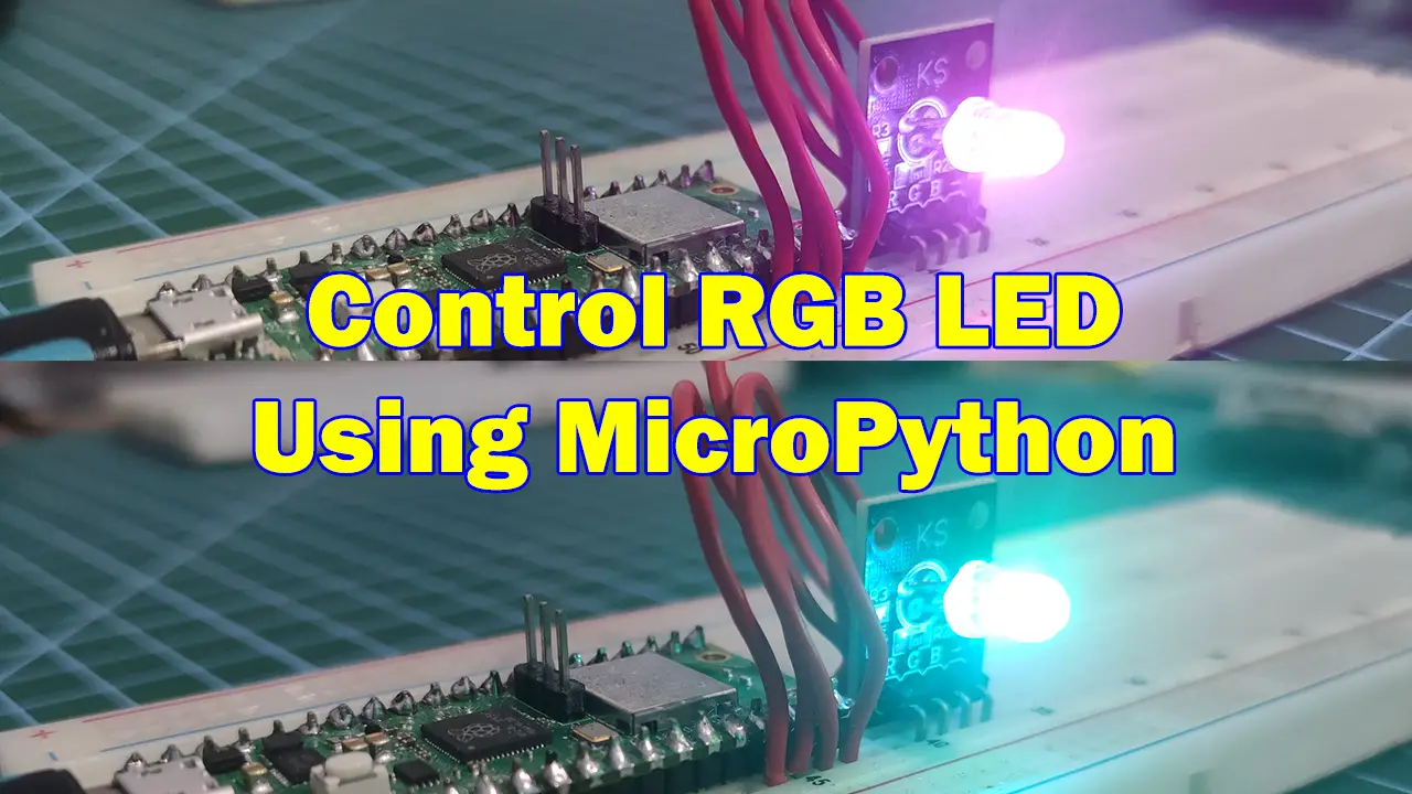
Do you want to know how to display your desired color using your RGB LED (Red/Green/Blue Light Emitting Diode) Module in MicroPython? This post will not only show you the basic of how to interface with this component but will show you how to program it to display the color of your choice.
If you want to see a video demo presentation of this project then please see below or watch it on my YouTube channel.
Why I wrote this post?
In one of my MicroPython projects, I wanted to use multiple LEDs to display multiple colors that would represent the status but that would add more components and wirings so I thought of using a single instance of RGB module and varying the color.
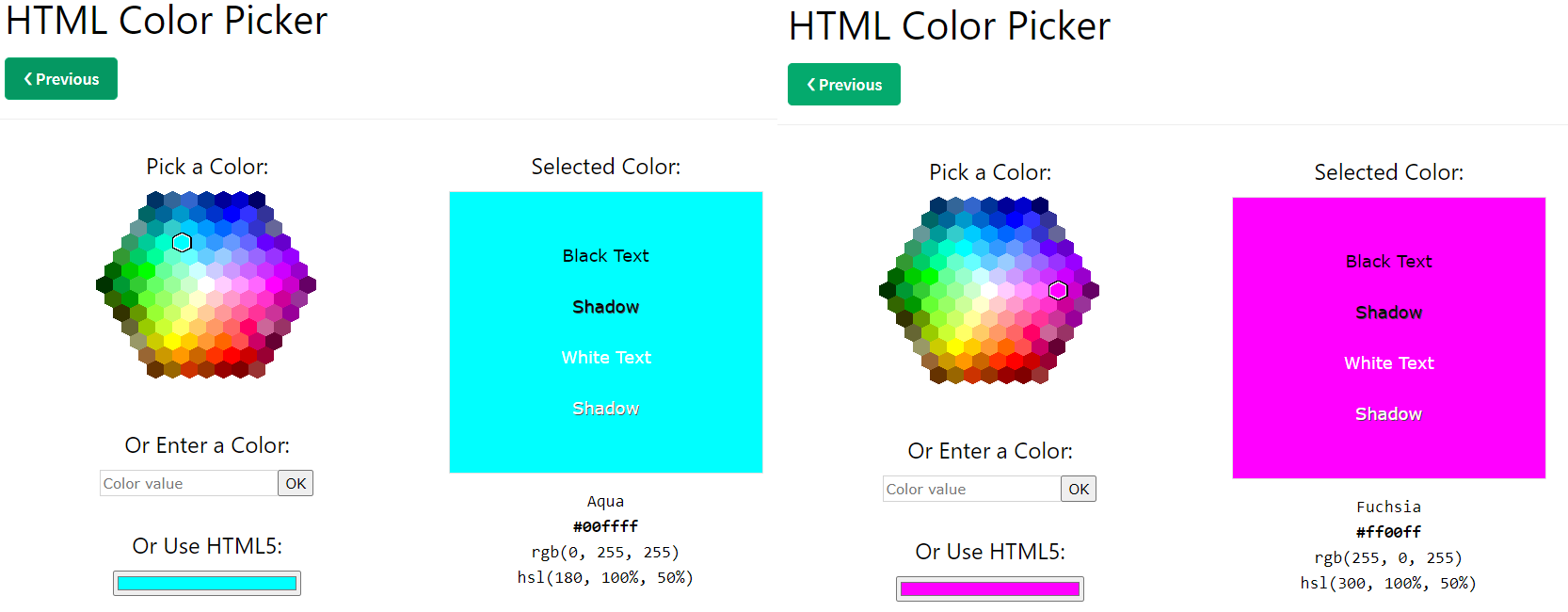
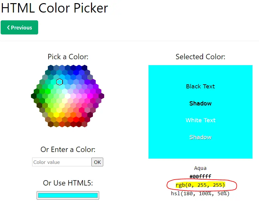
However, the colors that I would like to show are not just the typical Red-Green-Blue, and if you look at the color picker image below. What if I wanted to show a Fuschia(pink) or an Aqua(sky blue) in my RGB LED or violet with a color code of ##6600ff?
I looked over the internet but most of the articles were not able to solve my problem so I decided to share with you my custom solution on how to control your RGB module color with MicroPython.
Parts/Components Required
The following are the components required to follow along with this post.
- Raspberry Pi Pico W – Amazon | AliExpress
- or ESP32 – Amazon | AliExpress | Bangood
- or ESP8266 – Amazon | AliExpress | Bangood
- RGB Module – Amazon | AliExpress | Bangood
- Breadboard – Amazon | AliExpress | Bangood
- Connecting Wires – Amazon | AliExpress | Bangood
Disclosure: These are affiliate links and I will earn small commissions to support my site when you buy through these links.
I am using a Raspberry Pi Pico W as my development board in this post but the code is also applicable for an ESP32/ESP8266 board and all you have to do is update the GPIO pin assignment.
Prerequisites
You should have installed the latest MicroPython firmware for your device.
Related Content:
How to Install MicroPython firmware on Raspberry Pi Pico?
How to install MicroPython on ESP32 and download firmware
I am using the Thonny IDE in developing this project.
Related Content:
MicroPython Development Using Thonny IDE
How to guides in Thonny IDE using MicroPython
What is the RGB LED module?
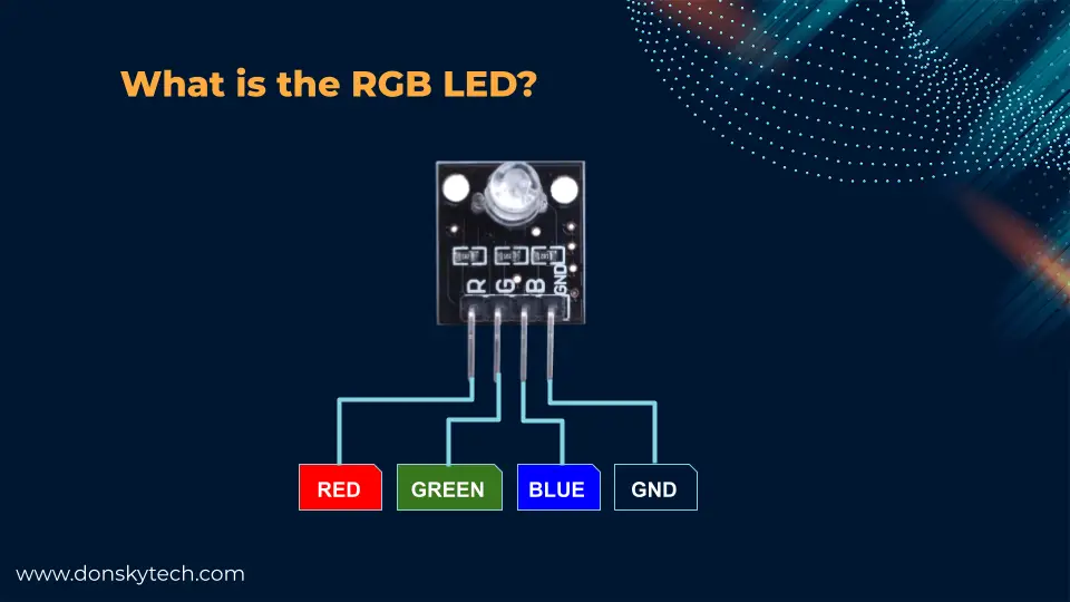
The RGB LED Module is actually a mixture of 3 LEDs (Red, Green, and Blue) packed in a single package. The module contains built-in current limiting resistors to prevent the LED from overcurrent. In order to achieve the desired color then you need to adjust the intensity of each individual LED.
RGB Module Specifications
Below are the common specifications of the usual RGB module that you would find in the market but check your component if you are not sure.
| Operating Voltage : | 5V |
| Mode : | Common Anode or Cathode |
| Number of Pins : | 4 |
| LED Diameter : | 5mm |
Wiring/Schematic
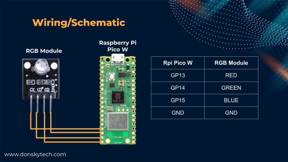
Above is the wiring/schematic for this post. You can choose the desired GPIO pins that you want in a Raspberry Pi Pico W board as all the GPIO pins can support Pulse Width Modulation (PWM).
RGB Model in a nutshell
The RGB color model is used to represent images in electronic systems. It stands for Red-Green-Blue which represents the primary colors from which the other colors can be derived. Think of it this way, if you have 3 cans of paint with colors Red, Green, and Blue then you can derive additional colors by mixing these colors.
If we go back to the color picker values for Aqua then you would notice that there is an RGB representation on the right-hand side of the screen. The values rgb(0, 255, 255) mean the same as RGB(RED, GREEN, BLUE). The range for each color is from 0 to 255 (inclusive). A value of zero means the absence of such color and 255 means the maximum. So to create an Aqua color then we need to mix GREEN and BLUE at maximum intensity with no trace of RED.
Pulse Width Modulation (PWM)

I was mentioning above about changing the intensity or the value of each color in an RGB model but how do we do that in our circuit? Enter PWM or Pulse Width Modulation which is a technique to approximately output analog signal from our digital pins. Microcontroller board GPIO pins usually output High and Low or either On or OFF. For our case, we can control how long a signal is High compared to its total period.
From the image above, the length of the blue arrow represents the Period of our signal and the red arrow is the length of our “On” time or Duty Cycle. A 20% duty cycle means the signal is high 20% of the time. 50% duty cycle means it is half on half off and 75% means it is on for 3/4 of the whole period.
This same technique is what we will be using to control the brightness or intensity of our LEDs and how we can come up with multiple colors from our RGM module.
How to control RGB LED with MicroPython?
Now so much for theory so it’s about time that we move forward and code this in MicroPython. We will start with the very basics and then move into how we can create the color that we want to be displayed by our RGB LED module. Make sure that your MicroPython device is now connected to your laptop thru the USB cable.
The code that I will be showing you in the following sections is available on my GitHub repository and you can either download it as a zip file or clone it with Git.
git clone https://github.com/donskytech/micropython-raspberry-pi-pico.git
cd rgb-module
Once downloaded then open the project in Thonny IDE. Upload all the files to the file system of your MicroPython device. If you are not sure how this is done then you can follow the How to upload files to your MicroPython Device using Thonny IDE?
Once uploaded then you can execute the below command to run the file that you would like to execute.
exec(open("basic_rgb_show.py").read())
exec(open("rgb_dim_brightness.py").read())
exec(open("custom_color.py").read())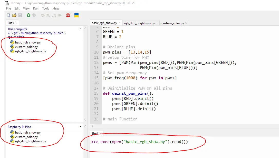
Display basic RGB color
import time
from machine import Pin,PWM

# RGB
RED = 0
GREEN = 1
BLUE = 2

# Declare pins
pwm_pins = [13,14,15]
# Setup pins for PWM
pwms = [PWM(Pin(pwm_pins[RED])),PWM(Pin(pwm_pins[GREEN])),
                PWM(Pin(pwm_pins[BLUE]))]
# Set pwm frequency
[pwm.freq(1000) for pwm in pwms]

# Deinitialize PWM on all pins
def deinit_pwm_pins():
    pwms[RED].deinit()
    pwms[GREEN].deinit()
    pwms[BLUE].deinit()

# main function
def main():
    while True:
        # Display RED
        pwms[RED].duty_u16(65535)
        pwms[GREEN].duty_u16(0)
        pwms[BLUE].duty_u16(0)
        time.sleep(1)

        # Display GREEN
        pwms[RED].duty_u16(0)
        pwms[GREEN].duty_u16(65535)
        pwms[BLUE].duty_u16(0)
        time.sleep(1)

        # Display BLUE
        pwms[RED].duty_u16(0)
        pwms[GREEN].duty_u16(0)
        pwms[BLUE].duty_u16(65535)
        time.sleep(1)

if __name__ == "__main__":
    try:
        main()
    except KeyboardInterrupt:
        deinit_pwm_pins()
The code above is how you can configure your MicroPython device to display the basic Red-Green-Blue color in your RGB module. Let us try going through the code.
import time
from machine import Pin,PWM
Import the necessary packages for pin set and PWM configurations.
# Declare pins
pwm_pins = [13,14,15]
# Setup pins for PWM
pwms = [PWM(Pin(pwm_pins[RED])),PWM(Pin(pwm_pins[GREEN])),
                PWM(Pin(pwm_pins[BLUE]))]
# Set pwm frequency
[pwm.freq(1000) for pwm in pwms]

# Deinitialize PWM on all pins
def deinit_pwm_pins():
    pwms[RED].deinit()
    pwms[GREEN].deinit()
    pwms[BLUE].deinit()
Next, we declare the pins that we are going to use and put them in a Python array for easier access then set up the PWM frequency using Python list comprehension. The deinit_pwm_pins() is needed so as to de-initialize the pins from outputting PWM.
# main function
def main():
    while True:
        # Display RED
        pwms[RED].duty_u16(65535)
        pwms[GREEN].duty_u16(0)
        pwms[BLUE].duty_u16(0)
        time.sleep(1)

        # Display GREEN
        pwms[RED].duty_u16(0)
        pwms[GREEN].duty_u16(65535)
        pwms[BLUE].duty_u16(0)
        time.sleep(1)

        # Display BLUE
        pwms[RED].duty_u16(0)
        pwms[GREEN].duty_u16(0)
        pwms[BLUE].duty_u16(65535)
        time.sleep(1)

if __name__ == "__main__":
    try:
        main()
    except KeyboardInterrupt:
        deinit_pwm_pins()
This is the main function of our program and as you can see we are controlling the intensity of the Red-Green-Blue LED lights by setting their duty cycle using the function duty_u16(). The values are between 0 to 65535 (inclusive) so zero means no lights at all while 65535 is full intensity.
We just deinitialize the PWM pins when we exit our program. That really is how you can configure the lights in an RGB module.
Control Brightness/Dim of RGB LED
If you google “MicroPython RGB LED” then some of the results will show you how to control the brightness of an LED.
import time
from machine import Pin,PWM

# RGB
RED = 0
GREEN = 1
BLUE = 2

# Declare pins
pwm_pins = [13,14,15]
# Setup pins for PWM
pwms = [PWM(Pin(pwm_pins[RED])),PWM(Pin(pwm_pins[GREEN])),
                PWM(Pin(pwm_pins[BLUE]))]
# Set pwm frequency
[pwm.freq(1000) for pwm in pwms]

def turn_off_rgb():
    pwms[RED].duty_u16(0)
    pwms[GREEN].duty_u16(0)
    pwms[BLUE].duty_u16(0)
    time.sleep(0.1)

# Deinitialize PWM on all pins
def deinit_pwm_pins():
    pwms[RED].deinit()
    pwms[GREEN].deinit()
    pwms[BLUE].deinit()

# main function
def main():
    while True:
        for pwm in pwms:
            # Turn off each RGB
            turn_off_rgb()

            for duty_value in range(0, 65535, 16):
                pwm.duty_u16(duty_value)
                time.sleep(0.001)

if __name__ == "__main__":
    try:
        main()
    except KeyboardInterrupt:
        deinit_pwm_pins()
The code is almost similar to what I have shown earlier so we will just show what is the difference.
def turn_off_rgb():
    pwms[RED].duty_u16(0)
    pwms[GREEN].duty_u16(0)
    pwms[BLUE].duty_u16(0)
    time.sleep(0.1)
This is just a convenience function that will turn off all RGB LEDs.
# main function
def main():
    while True:
        for pwm in pwms:
            # Turn off each RGB
            turn_off_rgb()

            for duty_value in range(0, 65535, 16):
                pwm.duty_u16(duty_value)
                time.sleep(0.001)

if __name__ == "__main__":
    try:
        main()
    except KeyboardInterrupt:
        deinit_pwm_pins()
In the main function, we can all of our PWM pins and then turn everything off for a clear display. Next, for each RGB LED pin, we do a loop between the minimum(zero) value to the maximum(65535) in a sequence of steps which is 16 so we start counting from 0, 16, 32, 64….. 65535, and then pause for some time.
Executing this code would vary the brightness or intensity of your RGB LED.
Show custom color
Now we get to the exciting part and the solution to my earlier problem on how to show custom color on my RGB LED using MicroPython.
The RGB color model theory section above then it might give you a hint about how we are going to show our own custom color in your RGB module. We only need to control the intensity of each RGB LED by setting the individual duty cycle. But your next question might be, what value of duty cycle should I put per each light? Read on about how you can figure this out in the code below.
import time
from machine import Pin,PWM

#RGB
RED = 0
GREEN = 1
BLUE = 2

# Declare pins
pwm_pins = [13,14,15]
# Setup pins for PWM
pwms = [PWM(Pin(pwm_pins[RED])),PWM(Pin(pwm_pins[GREEN])),
                PWM(Pin(pwm_pins[BLUE]))]
# Set pwm frequency
[pwm.freq(1000) for pwm in pwms]

# Colors that we are going to display
colors = {"pink": (255, 0, 255), "yellow": (255,255,0), "skyblue": (0, 255, 255)
          , "orange": (230, 138 , 0), "white": (255, 255 , 255)}

def map_range(x, in_min, in_max, out_min, out_max):
  return (x - in_min) * (out_max - out_min) // (in_max - in_min) + out_min

def turn_off_rgb():
    pwms[RED].duty_u16(0)
    pwms[GREEN].duty_u16(0)
    pwms[BLUE].duty_u16(0)
    time.sleep(0.1)

# Deinitialize PWM on all pins
def deinit_pwm_pins():
    pwms[RED].deinit()
    pwms[GREEN].deinit()
    pwms[BLUE].deinit()

# main function
def main():
    while True:
        for key, color in colors.items():
            # Turn off each RGB
            turn_off_rgb()

            print(f"Displaying Color:: {key}")
            red, green, blue = color

            pwms[RED].duty_u16(map_range(red, 0, 255, 0, 65535))
            pwms[GREEN].duty_u16(map_range(green, 0, 255, 0, 65535))
            pwms[BLUE].duty_u16(map_range(blue, 0, 255, 0, 65535))
            time.sleep(2)


if __name__ == "__main__":
    try:
        main()
    except KeyboardInterrupt:
        deinit_pwm_pins()
import time
from machine import Pin,PWM

#RGB
RED = 0
GREEN = 1
BLUE = 2

# Declare pins
pwm_pins = [13,14,15]
# Setup pins for PWM
pwms = [PWM(Pin(pwm_pins[RED])),PWM(Pin(pwm_pins[GREEN])),
                PWM(Pin(pwm_pins[BLUE]))]
# Set pwm frequency
[pwm.freq(1000) for pwm in pwms]
This is similar to the earlier code that I have shown above.
# Colors that we are going to display
colors = {"pink": (255, 0, 255), "yellow": (255,255,0), "skyblue": (0, 255, 255)
          , "orange": (230, 138 , 0), "white": (255, 255 , 255)}

def map_range(x, in_min, in_max, out_min, out_max):
  return (x - in_min) * (out_max - out_min) // (in_max - in_min) + out_min
The colors dictionary object will represent the colors that we want to show and the corresponding RGB values represented in a Python tuple. So for this "pink": (255, 0, 255) entry in our dictionary, it will map to the following "color": (RED, GREEN, BLUE)
The map_range function is similar to the Arduino map function if you have done some Arduino coding.
/* Map an analog value to 8 bits (0 to 255) */
void setup() {}

void loop() {
  int val = analogRead(0);
  val = map(val, 0, 1023, 0, 255);
  analogWrite(9, val);
}
The only difference is that we are going to map the values of 0-255 to the duty cycle from 0-65535. If you run this code in the REPL prompt or the shell terminal of your IDE then you would see the following output.
>>> def map_range(x, in_min, in_max, out_min, out_max):
    return (x - in_min) * (out_max - out_min) // (in_max - in_min) + out_min

>>> map_range(0, 0, 255, 0, 65535)
0
>>> map_range(255, 0, 255, 0, 65535)
65535
>>> map_range(127, 0, 255, 0, 65535)
32639
I hope you are getting where this code is going but if not then just read on. 🙂
def turn_off_rgb():
    pwms[RED].duty_u16(0)
    pwms[GREEN].duty_u16(0)
    pwms[BLUE].duty_u16(0)
    time.sleep(0.1)

# Deinitialize PWM on all pins
def deinit_pwm_pins():
    pwms[RED].deinit()
    pwms[GREEN].deinit()
    pwms[BLUE].deinit()
The two functions above would just turn off the RGB LED and deinitialize the PWM setup.
# main function
def main():
    while True:
        for key, color in colors.items():
            # Turn off each RGB
            turn_off_rgb()

            print(f"Displaying Color:: {key}")
            red, green, blue = color

            pwms[RED].duty_u16(map_range(red, 0, 255, 0, 65535))
            pwms[GREEN].duty_u16(map_range(green, 0, 255, 0, 65535))
            pwms[BLUE].duty_u16(map_range(blue, 0, 255, 0, 65535))
            time.sleep(2)


if __name__ == "__main__":
    try:
        main()
    except KeyboardInterrupt:
        deinit_pwm_pins()
Now, this is where the magic would happen. We loop through each color that we want to display then we initially turn off all the RGB LEDs. We extract the tuple of RGB color and for each Red/Green/Blue LED, we set the duty cycle by mapping the values of 0-255 into 0-65535. That really is how you can choose your desired color
Wrap Up
In this post, we have successfully configured our RGB LED to display the desired color that we want using MicroPython. Using this simple exercise, you will learn a lot about how to program in MicroPython.
I hope you learn something. Happy Exploring!
Read Next:
Building a MicroPython Wifi Robot Car
Pico W -MicroPython MQTT – BMP/BME 280 Weather Station
Support Me!
I love sharing what I know and hopefully, I was able to help you. Writing helpful content takes so much time and research. If you think you like my work and I have managed to help you then please consider supporting my channel. I would be very grateful and would boost my confidence that what I am doing is making a big change in the world. (No Pun Intended!) 😉
Become a Patron!
Leave a Reply