Introduction
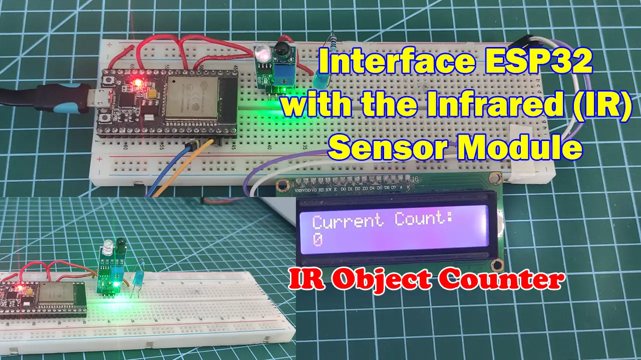
Do you have an Internet of Things (IoT) project that needs to detect the movement or proximity of an object from another object? Using an Infrared (IR) sensor could solve this problem together with the WiFi capability of the ESP32 microcontroller. We will program our ESP32 using the Arduino framework and create two practical IoT projects using this IR sensor.
If you want to see a demo of this project then please see the below video or watch it on my YouTube channel.
What is an Infrared (IR) Sensor?
The IR sensor is a passive electronic component popular with hobbyists and electronic enthusiasts. If ever you have built an Arduino obstacle avoidance robot car then chances are that you have used this component. Using this sensor we could check the proximity of one object with another and react accordingly.
In fact, in a previous ESP8266 Webserver Conveyor Counter project, we created a prototype cardboard conveyor project that counts the number of items passing through it. We have utilized the IR sensor as an object counter on that project using an ESP8266 but we have not discussed much how it works. In this post, I will try to explain how to program the IR sensor as an object counter using an ESP32 microcontroller.
IR Sensor Pinout
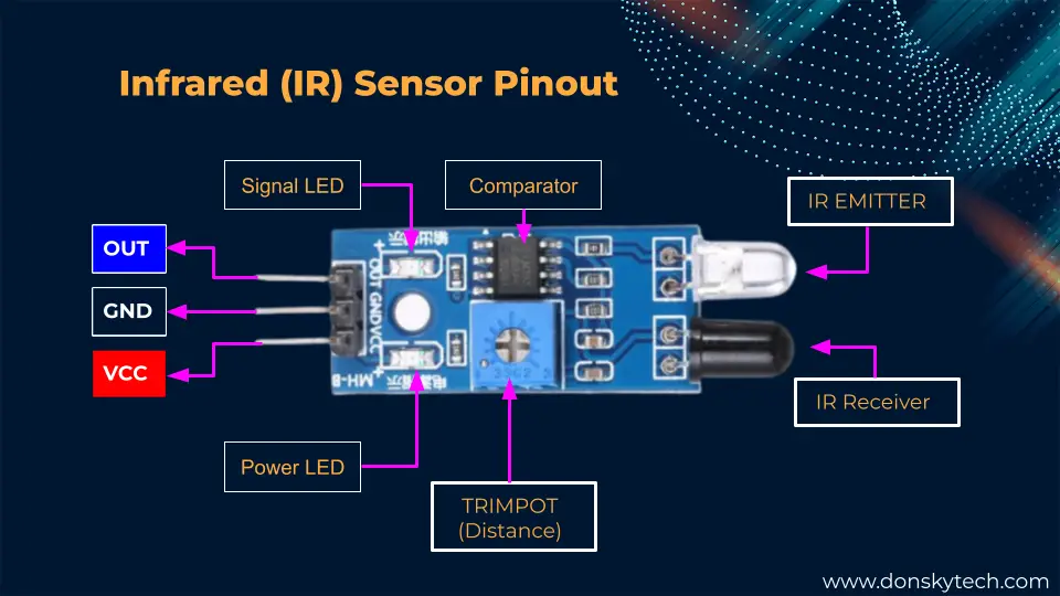
The Infrared (IR) sensor contains three pins for connections mainly the VCC, GND, and the Output pin. The VCC is attached to the 5V, the GND is to the GND, and the Output pin is to any of the GPIO of the ESP32.
Most modules come with an Infrared (IR) Emitter, an IR Receiver, and a Trimpot potentiometer to adjust the distance sensitivity between it and the objects being detected.
It also contains an onboard LED (Light Emitting Diode) and Power LED to display if power is properly applied and if an object is detected. The Op-amp comparator chip is needed to process the incoming signal from the photodiode to a digital signal.
How do Infrared sensors work?
The image above shows how the IR sensor detects the movement and proximity of our object.
Power is applied to the Infrared (IR) Emitter diode to emit infrared light and if an object or load is near then it gets reflected back to the Infrared (IR) receiver which is usually a Photodiode. The nearer the object the stronger the signal is captured. A LOW signal is returned by our Infrared (IR) sensor to our ESP32 Microcontroller which can be detected by any of its GPIO pins.
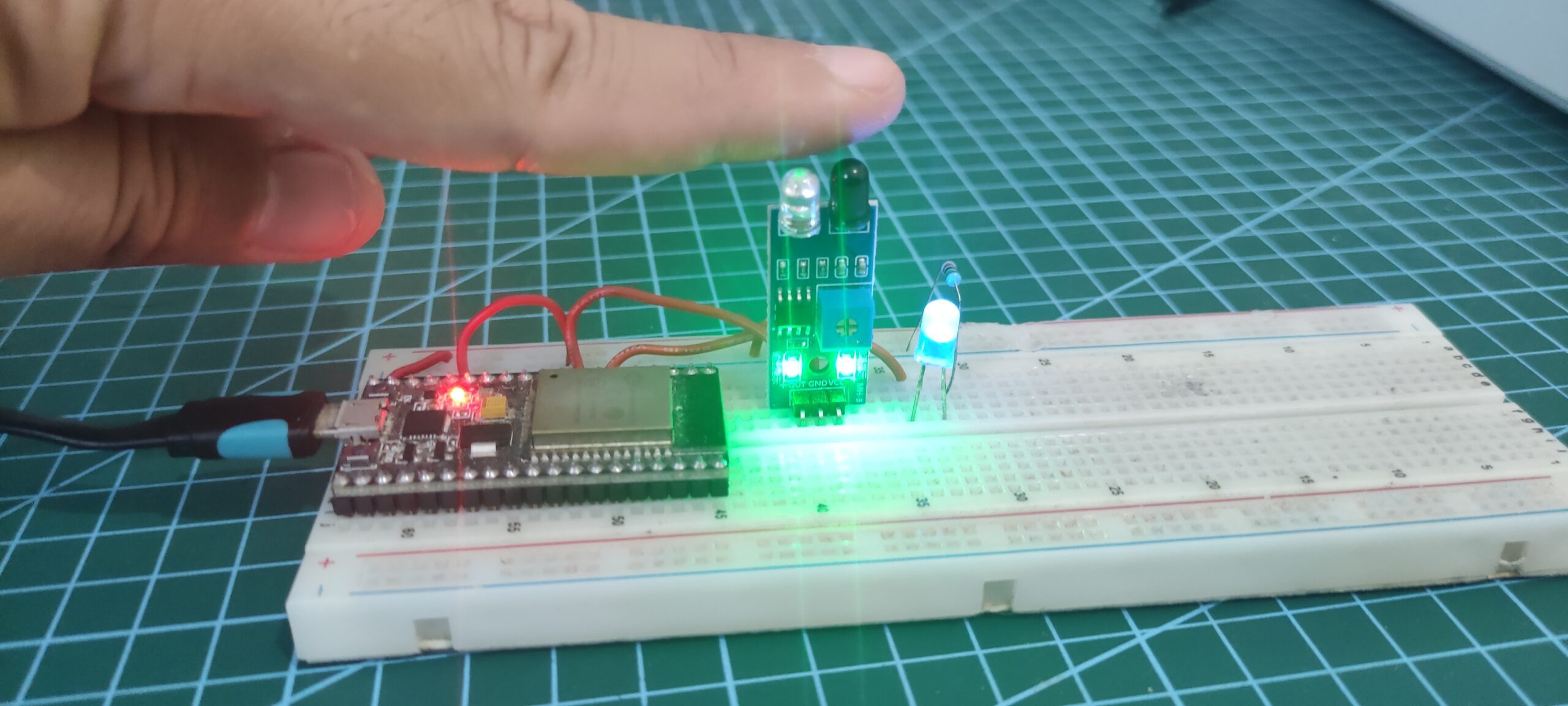
Can you see infrared light?
I often get asked if I can see the Infrared Light being emitted by the Infrared (IR) sensor. Unfortunately, you cannot see it with your naked eye but if you video it with your mobile phone then you would see the pinkish glow. If you are curious then please see this video below. 🙂
Parts/Components
The following are the components required to follow along with this post.
- ESP32 – Amazon | AliExpress | Bangood
- Infrared (IR) Sensor Module – Amazon | AliExpress
- LED – Amazon | AliExpress | Bangood
- Resistor (220 Ohms) – Amazon | AliExpress | Bangood
- Breadboard – Amazon | AliExpress | Bangood
- Connecting Wires – Amazon | AliExpress | Bangood
Disclosure: These are affiliate links and I will earn small commissions to support my site when you buy through these links.
Prerequisites
I have used Visual Studio Code with PlatformIO extensions in developing this project but you can still use the Arduino IDE the same way.
Related Content:
PlatformIO Tutorial for Arduino Development
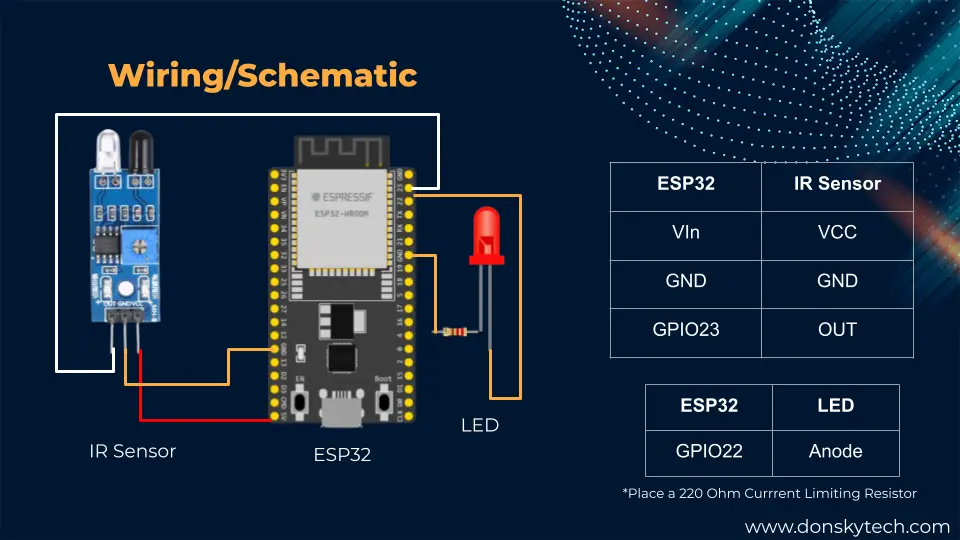
Wiring/Schematics
The below images would show you the wiring and schematic needed to follow along with this post.
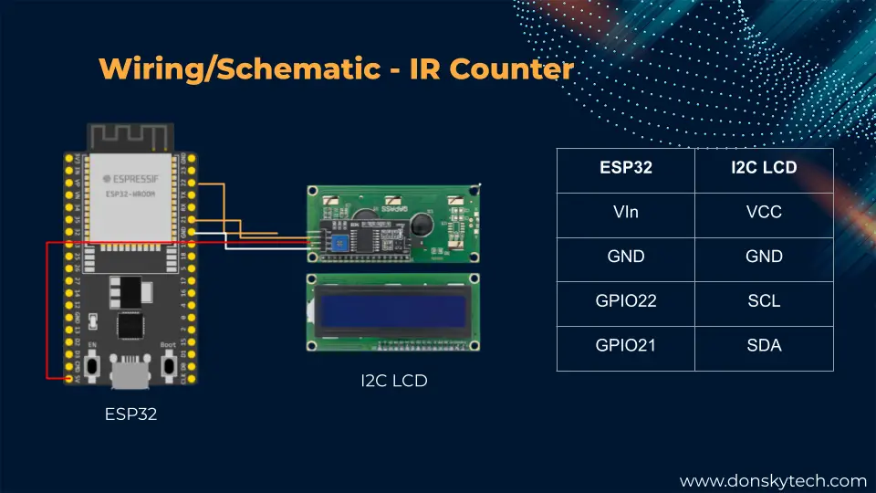
Below is the wiring for the I2C LCD display. The wiring for the IR Sensor with the ESP32 remains the same.
How to control an Infrared (IR) Sensor with ESP32 and Arduino?
Let us go into the exciting part about how we could control our Infrared (IR) Sensor with our ESP32 microcontroller using the Arduino framework. We are going to create two simple projects that will display how useful this electronic component is.
The first one is a simple IR Sensor switch that will turn on or off an LED depending on if the IR sensor can detect an object. The second one is how to use the IR sensor as an object counter that will count how many objects it can detect.
The code for this project is available on my GitHub repository and you can either download it as a zip file or clone it using Git.
git clone https://github.com/donskytech/platformio-projects.git
cd esp32-projects/esp32-infrared-sensor/
Open the project in Visual Studio Code with PlatformIO IDE extension installed or you can use the Arduino IDE 2 if you want.
IR Sensor as a simple switch
This code is available as loop_ir.cpp.txt in the project and you could copy this in the main.cpp of your PlatformIO project. If you are using Arduino IDE then just copy this into a new sketch.
/*
  Project: Read IR Sensor
  Author: donsky
  For: www.donskytech.com
  Date: April 30, 2023
*/

#include <Arduino.h>

const int irSensor = 33;
const int ledPin = 32;

int irReading;

void setup()
{
  Serial.begin(115200);
  pinMode(irSensor, INPUT);
  pinMode(ledPin, OUTPUT);
}
void loop()
{
  irReading = digitalRead(irSensor);
  if (irReading == LOW)
  {
    digitalWrite(ledPin, HIGH);
  }
  else
  {
    digitalWrite(ledPin, LOW);
  }
}
The code above will turn on or turn off the attached LED whenever the IR sensor detects that something is near it.
/*
  Project: Read IR Sensor
  Author: donsky
  For: www.donskytech.com
  Date: April 30, 2023
*/

#include <Arduino.h>

const int irSensor = 33;
const int ledPin = 32;

int irReading;
First, we define the GPIO pins where our IR sensor and LED are connected and we initialize a global variable called irReading which will hold the current value of the sensor.
void setup()
{
  Serial.begin(115200);
  pinMode(irSensor, INPUT);
  pinMode(ledPin, OUTPUT);
}
After that, we initialize our serial monitor baud rate and configure each of our GPIO pins for input and output. We are going to read the digital output from our IR sensor so we configure it for input while the LED pin is only for output purposes.
void loop()
{
  irReading = digitalRead(irSensor);
  if (irReading == LOW)
  {
    digitalWrite(ledPin, HIGH);
  }
  else
  {
    digitalWrite(ledPin, LOW);
  }
}
The function loop() will just periodically read the output of our IR sensor and depending on the reading then it will turn on or off the LED. If no object is detected by the IR sensor then it would output a HIGH value while it would transition to a LOW reading when an object is near it.
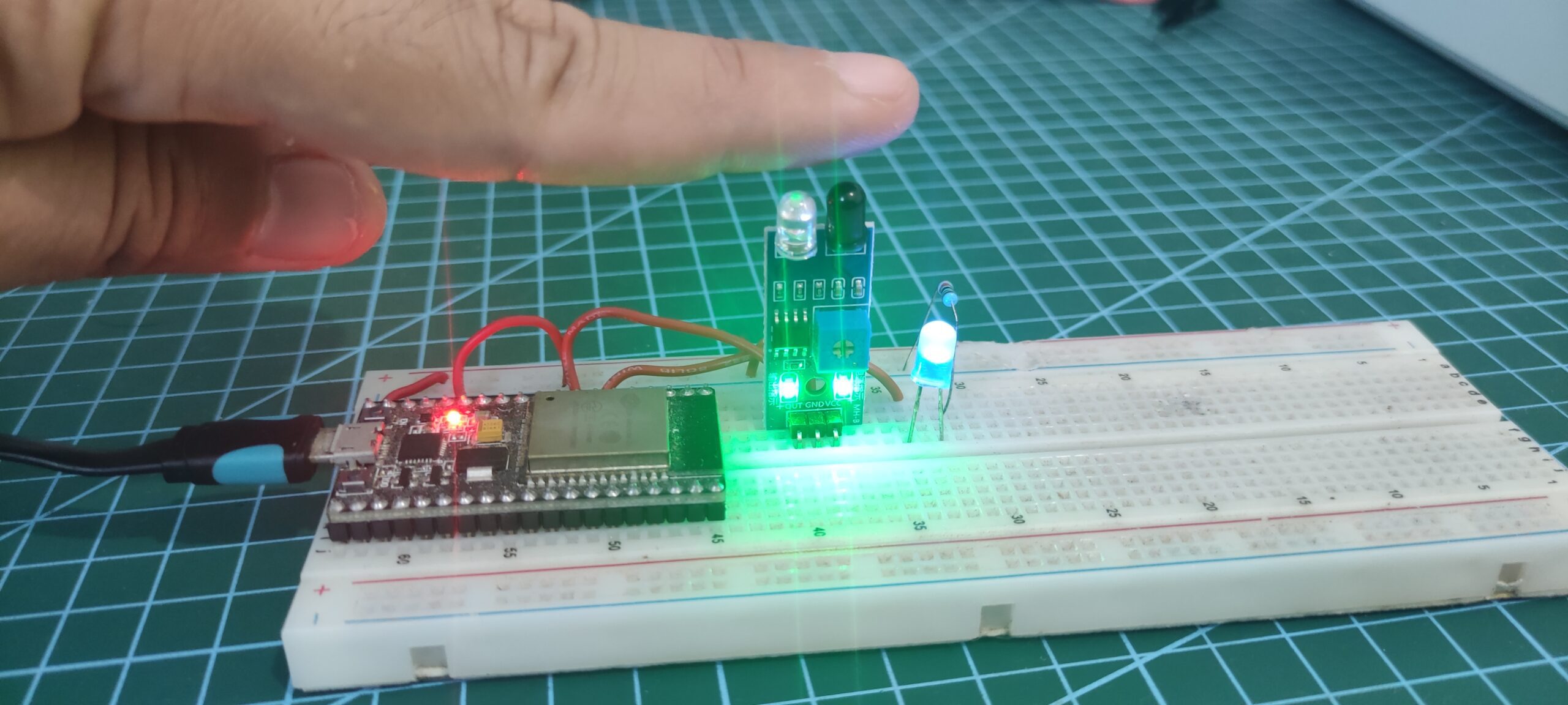
If everything works correctly then the LED should automatically turn on or off depending on if our IR sensor can detect if an object is near it or not.
One major drawback of the code above is that our loop function continually runs even if no object is present. This might be a waste of computing power of our ESP32 microcontroller especially if it needs to control other components. One option is to use interrupt where we would listen for any changes from the readings of our IR Sensor.
You will see an example of how you can leverage the ESP32 interrupt on the next project.
IR sensor as object counter
This code is available as ir_sensor_counter.cpp.txt in the project and you could copy this in the main.cpp of your PlatformIO project. If you are using Arduino IDE then just copy this into a new sketch.
/*
  Project: IR Sensor Counter
  Author: donsky
  For: www.donskytech.com
  Date: April 30, 2023
*/

#include <Arduino.h>
#include <LiquidCrystal_I2C.h>

const int IR_Sensor = 33;

volatile uint64_t count = 0;
volatile uint64_t currentCount = -1;

unsigned long currentTime = 0;
unsigned long lastReadTime = 0;
unsigned int intervalDelay = 1000;

void IRAM_ATTR isr()
{
  currentTime = millis();
  // IR Sensor is noisy so we add a debounce mechanism here
  if (currentTime - lastReadTime > intervalDelay)
  {
    count++;
    lastReadTime = currentTime;
  }
}

// set the LCD number of columns and rows
int lcdColumns = 16;
int lcdRows = 2;

// Check your I2C LCD Address
LiquidCrystal_I2C lcd(0x27, lcdColumns, lcdRows);

// Function to print to LCD
void printToLCD(const String &message, uint8_t column, uint8_t row, bool isClear)
{
  if (isClear)
  {
    lcd.clear();
  }
  // set cursor to  column,  row
  lcd.setCursor(column, row);
  if (message.length() == 0)
  {
    lcd.setCursor(0, 1);
    for (int n = 0; n < 16; n++)
    {
      lcd.print(" ");
    }
  }
  else
  {
    lcd.print(message);
  }
}

void setup()
{
  Serial.begin(115200);
  pinMode(IR_Sensor, INPUT);
  attachInterrupt(digitalPinToInterrupt(IR_Sensor), isr, FALLING);

  lcd.init();
  lcd.clear();
  lcd.backlight(); // Make sure backlight is on
  printToLCD("Current Count:", 0, 0, false);
  delay(1000);
}
void loop()
{
  Serial.printf("Count :: %lld\r\n", count);
  if (currentCount != count)
  {
    currentCount = count;
    char buffer[50];
    ltoa(count, buffer, 10);
    // Print a message to the LCD.
    printToLCD(buffer, 0, 1, false);
  }
}
The code above will show how we can utilize the IR sensor as an object counter. In addition, we can display the count in an LCD display. Let us try to go over the code for you to learn what each part of it does.
Initialize global variables
#include <Arduino.h>
#include <LiquidCrystal_I2C.h>

const int IR_Sensor = 33;

volatile uint64_t count = 0;
volatile uint64_t currentCount = -1;

unsigned long currentTime = 0;
unsigned long lastReadTime = 0;
unsigned int intervalDelay = 1000;
The first two lines import our Arduino and LCD header file which will drive our I2C LCD. Next, we define our GPIO PIN for our IR sensor.
We created two variables that will hold the count of our IR sensor. Take note that we define them as volatile as we need to read them in memory instead of reading from the register as we will be using interrupt here.
The variables currentTime, lastReadTime , and intervalDelay are used for debouncing the IR sensor module. This module is a “noisy” sensor similar to a switch so debouncing them is needed to get a constant response. When I say noisy, it means that the sensor bounces from HIGH to LOW to HIGH to LOW again when an object is near it until it settles into its final value.
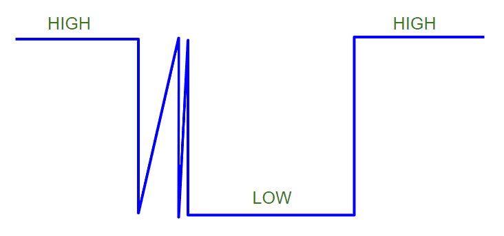
If you are expecting a smooth transition when the IR sensor detects an object then you would be surprised. We need to handle this debouncing issue so I have added code to handle this later.
Define our Interrupt function
void IRAM_ATTR isr()
{
  currentTime = millis();
  // IR Sensor is noisy so we add a debounce mechanism here
  if (currentTime - lastReadTime > intervalDelay)
  {
    count++;
    lastReadTime = currentTime;
  }
}
When the IR sensor detects an object it calls this function named isr(). This function is an Interrupt Service Routine that gets called when the IR sensor transitions from HIGH to LOW.
Setup our I2C LCD
// set the LCD number of columns and rows
int lcdColumns = 16;
int lcdRows = 2;

// Check your I2C LCD Address
LiquidCrystal_I2C lcd(0x27, lcdColumns, lcdRows);

// Function to print to LCD
void printToLCD(const String &message, uint8_t column, uint8_t row, bool isClear)
{
  if (isClear)
  {
    lcd.clear();
  }
  // set cursor to  column,  row
  lcd.setCursor(column, row);
  if (message.length() == 0)
  {
    lcd.setCursor(0, 1);
    for (int n = 0; n < 16; n++)
    {
      lcd.print(" ");
    }
  }
  else
  {
    lcd.print(message);
  }
}
The code above will control our I2C LCD Display and will print the current count of our IR sensor object counter.
Related Content:
How to use the Arduino I2C Scanner?
setup()
void setup()
{
  Serial.begin(115200);
  pinMode(IR_Sensor, INPUT);
  attachInterrupt(digitalPinToInterrupt(IR_Sensor), isr, FALLING);

  lcd.init();
  lcd.clear();
  lcd.backlight(); // Make sure backlight is on
  printToLCD("Current Count:", 0, 0, false);
  delay(1000);
}
The function setup() initializes many of the aspects of our program. We begin by initializing the serial monitor baud rate. Next, we attached an interrupt to our IR sensor pin and declared our function isr() , and listen to the Falling event.
The Falling event will occur when the IR sensor detects an object and it transitions from a HIGH reading to a LOW. The function isr() would then be called to increase our current count.
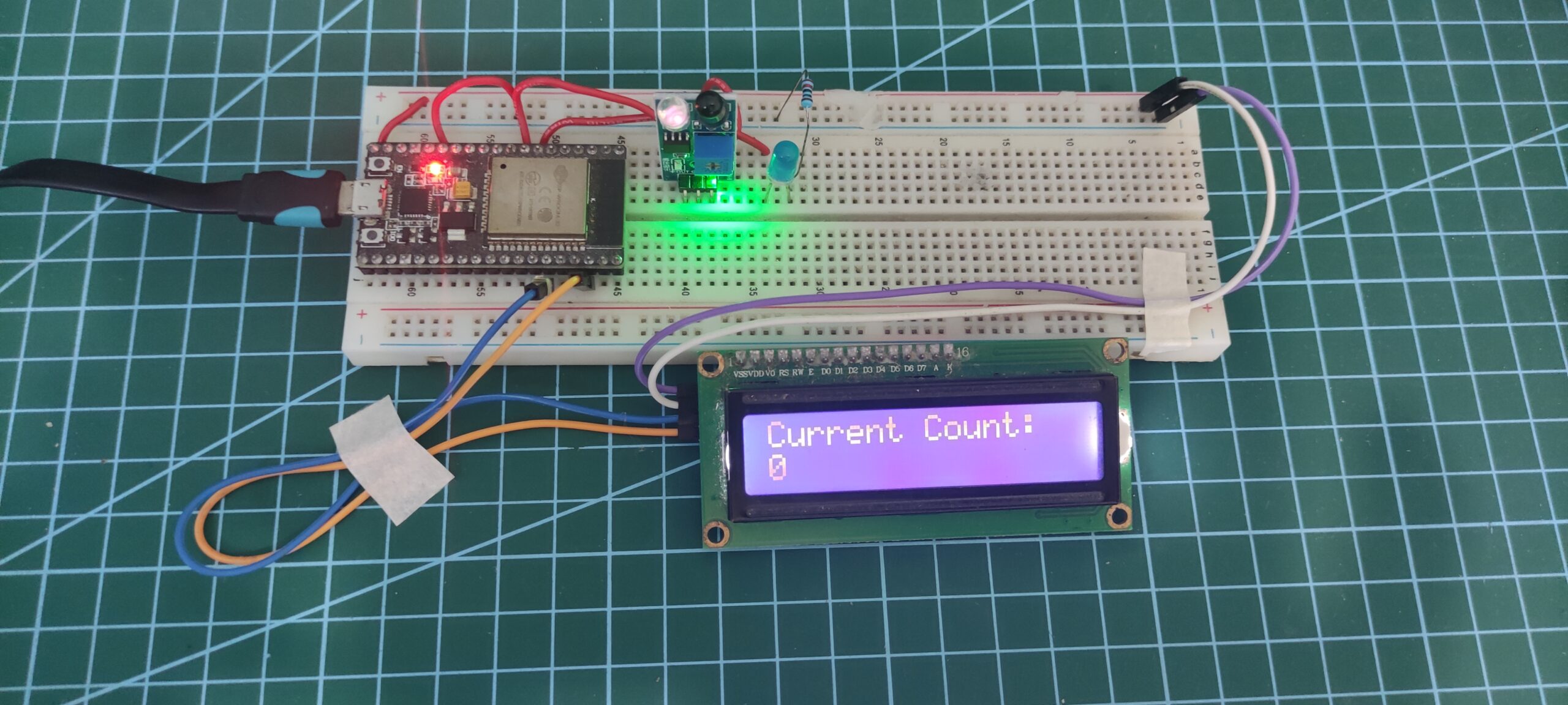
Lastly, we initialize our I2C LCD display and print the current count on the first row.
loop()
void loop()
{
  Serial.printf("Count :: %lld\r\n", count);
  if (currentCount != count)
  {
    currentCount = count;
    char buffer[50];
    ltoa(count, buffer, 10);
    // Print a message to the LCD.
    printToLCD(buffer, 0, 1, false);
  }
}
The function loop() will periodically print the current count into our I2C LCD. The variables currentCount and count are compared so that we won’t need to display the same number to our I2C LCD multiple times.
Can you see how easy it is to use this IR sensor as an object counter in your IoT projects?
Wrap Up
We have discussed how to interface an ESP32 microcontroller with the infrared (IR) sensor in this post. I have shown you the different ways to utilize this excellent component on your IoT projects.
I hope you learned something! Happy Exploring!
Read Next:
Create your own ESP32 Wifi Car using the library esp32-wifi-car
Building a MicroPython Wifi Robot Car
Support Me!
I love sharing what I know and hopefully, I was able to help you. Writing helpful content takes so much time and research. If you think you like my work and I have managed to help you then please consider supporting my channel. I would be very grateful and would boost my confidence that what I am doing is making a big change in the world. (No Pun Intended!) 😉
Become a Patron!
Leave a Reply