Introduction
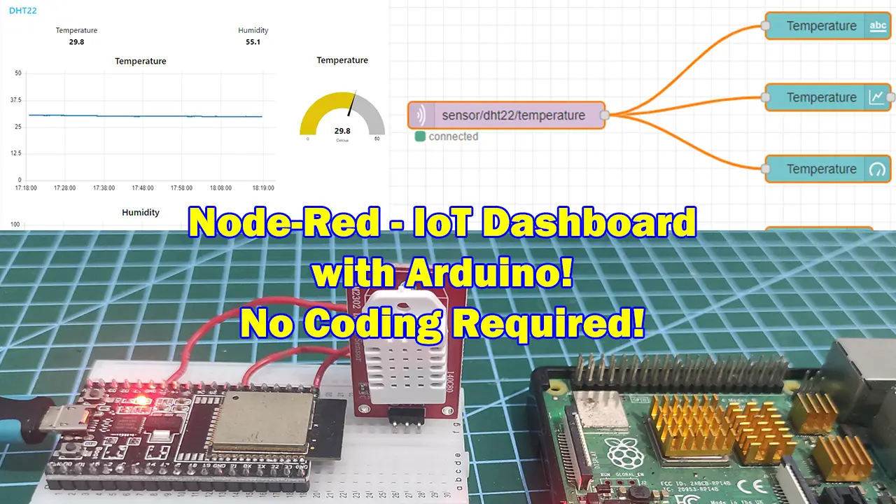
This post will show you how to set up Node-Red to create your own Internet of Things (IoT) dashboard to display Arduino sensor readings without doing any low-level coding like HTML/CSS/Javascript.
If you want to see a video demo presentation of this project then please see below or watch it on my YouTube channel.
What are we building?
If you do not have any Web Development experience then developing an IoT dashboard might seem trivial and hard as you need some knowledge of HTML/CSS/Javascript. Fortunately, Node-Red is a low-code browser-based programming tool that will allow us to generate our own user interface with minimal coding or nothing at all.
In this post, we will configure Node-Red to handle the sensor readings coming from my ESP32 board that reads the DHT22 sensor module. We will be programming the ESP32 with the Arduino framework and sending the messages thru MQTT (MQ Telemetry Transport)
Design
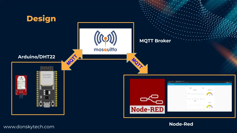
The image above shows the overall design of this project and which is composed of the following three major components
- Arduino – the source of our sensor readings and in this case we are using the DHT22 sensor.
- Mosquitto – our MQTT broker
- Node-Red – contains our flows that will display our sensor readings thru MQTT
I have used an ESP32 board and a DHT22 sensor in this post to retrieve the temperature and humidity using the Arduino framework and sent them thru MQTT topics.
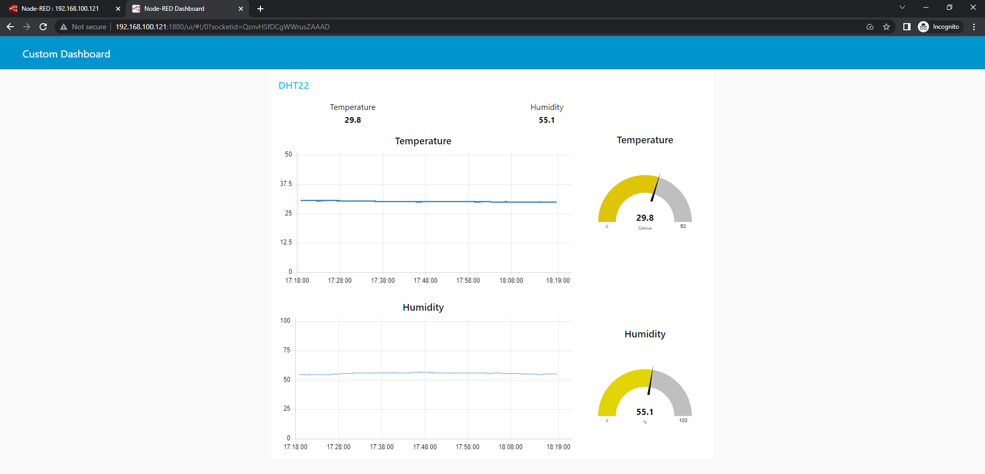
The sensor readings are sent thru MQTT messages and are received by the Mosquitto broker. The Node-Red is configured to listen to the same MQTT topics from the Arduino code and has a flow that displays the readings in a dashboard that automatically updates itself.
Prerequisites
You should have access to a Node-Red application or you can set up your own. I am using my Raspberry Pi as my host and installed the Node-Red in it.
Related Content:
How to install Node-Red on Raspberry Pi
How to install Node-Red on Windows or PC
Also, you need to have an MQTT broker where you could publish messages. I am using the Mosquitto MQTT broker on my Windows or PC workstation.
Related Content:
Install Mosquitto MQTT Windows
For the Arduino code, I have used Visual Studio Code with PlatformIO extensions but you could use the Arduino IDE if you prefer that.
Related Content:
PlatformIO Tutorial for Arduino Development
Parts/Components Required
To follow along with this post then you need the following parts and components:
- ESP32 – Amazon | AliExpress | Bangood
- Raspberry Pi 4B – Amazon | AliExpress
- DHT22 Sensor Module – Amazon | AliExpress
- Breadboard – Amazon | AliExpress | Bangood
- Connecting Wires – Amazon | AliExpress | Bangood
Disclosure: These are affiliate links and I will earn small commissions to support my site when you buy through these links.
Wiring/Schematic
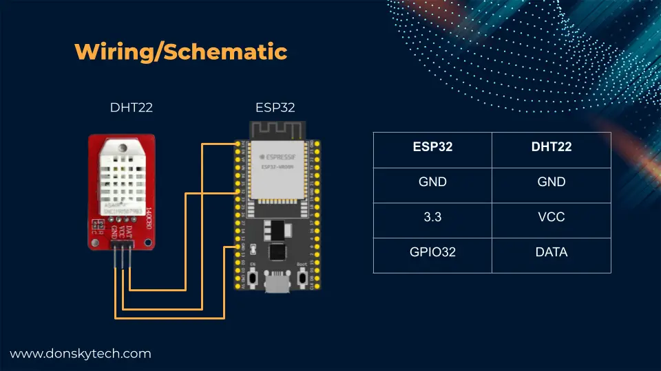
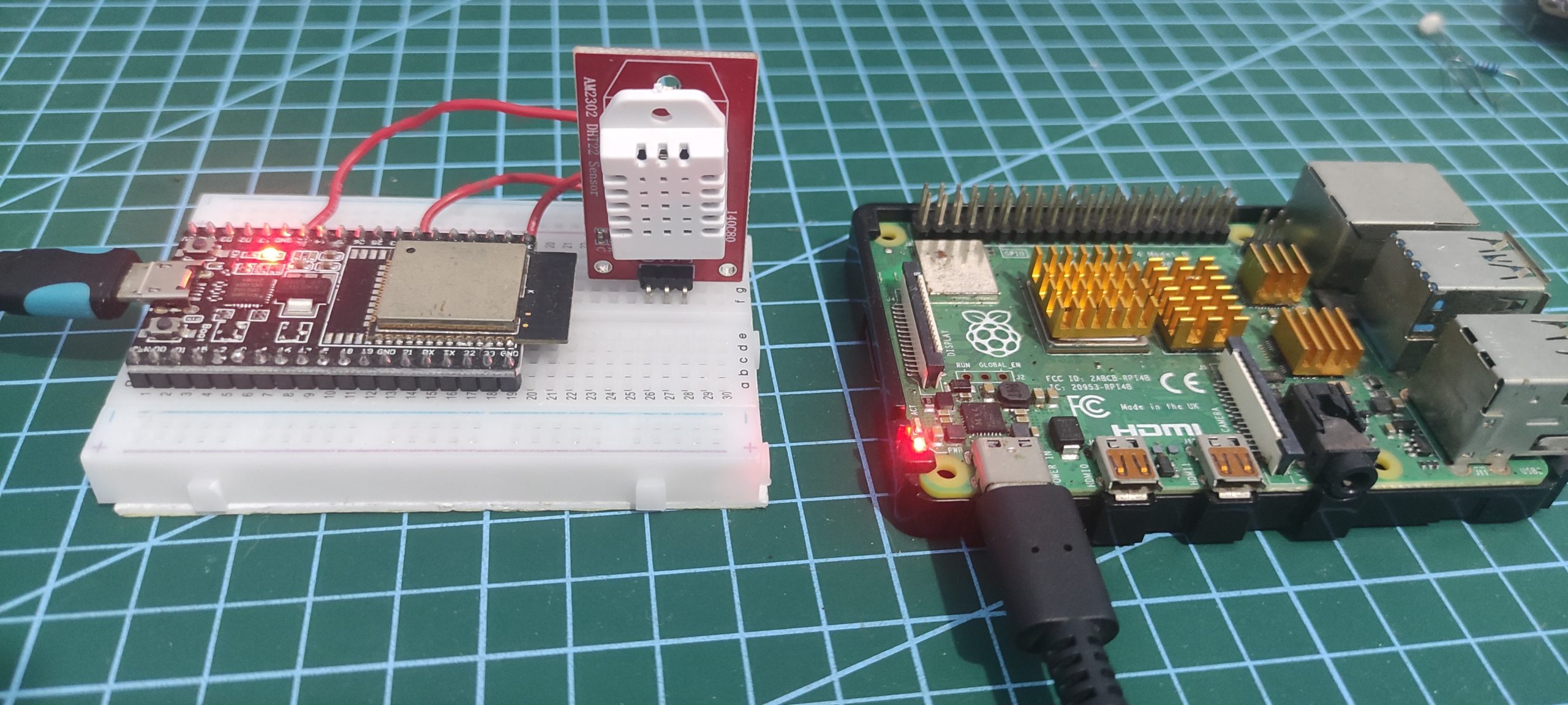
The above image shows the wiring of our Arduino ESP32 code with our DHT22 sensor.
Related Content:
ESP32 – Read DHT22 Sensor using Arduino
ESP32 Arduino Code
The code for this project is available in my GitHub repository which you can download as a zip file or clone it using Git. When the download is finished, open this project in Visual Studio Code with PlatformIO extensions installed.
git clone https://github.com/donskytech/platformio-projects.git
cd esp32-projects/esp32-mqtt-dht22/
The main.cpp file contains the meat of our logic and is shown below and will do the following functions:
- Connect to our WiFi
- Read our DHT22 sensor module
- Publish an MQTT message to our Mosquitto broker
This file will communicate with our Mosquitto broker so that the MQTT messages are received by our Node-Red application and display the Arduino sensor readings in a graphical chart that gets updated asynchronously in real-time.
I have used PubSubClient to communicate with our Mosquitto MQTT broker in this post. If you are not familiar with this library or how to communicate with an MQTT broker with Arduino then please see the below post.
Related Content:
MQTT Tutorial using Arduino Framework
#include <Arduino.h>
#include "DHT.h"
#include <WiFi.h>
#include <PubSubClient.h>

#define DHTPIN 32 // Digital pin connected to the DHT sensor

// Uncomment whatever type you're using!
// #define DHTTYPE DHT11   // DHT 11
#define DHTTYPE DHT22 // DHT 22  (AM2302), AM2321
// #define DHTTYPE DHT21   // DHT 21 (AM2301)

// Initialize DHT sensor.
DHT dht(DHTPIN, DHTTYPE);

// Change this to point to your Wifi Credentials
const char *ssid = "<REPLACE_ME_WITH_YOUR_SSID>";
const char *password = "<REPLACE_ME_WITH_YOUR_PASSWORD>";

// Your MQTT broker ID
const char *mqttBroker = "192.168.100.22";
const int mqttPort = 1883;

// MQTT topics
const char *temperatureTopic = "sensor/dht22/temperature";
const char *humidityTopic = "sensor/dht22/humidity";

// MQTT Client
WiFiClient espClient;
PubSubClient client(espClient);

#define MSG_BUFFER_SIZE (5)

// Cycle time
unsigned long previousMillis = 0;
const int interval = 2000;

// Callback function whenever an MQTT message is received
void callback(char *topic, byte *payload, unsigned int length)
{
  Serial.print("Message arrived [");
  Serial.print(topic);
  Serial.print("] ");
  String message;
  for (int i = 0; i < length; i++)
  {
    Serial.print(message += (char)payload[i]);
  }
  Serial.println();
}

void reconnect()
{
  // Loop until we're reconnected
  while (!client.connected())
  {
    Serial.print("Attempting MQTT connection...");

    // Create a random client ID
    String clientId = "ESP32Client-";
    clientId += String(random(0xffff), HEX);

    // Attempt to connect
    if (client.connect(clientId.c_str()))
    {
      Serial.println("MQTT Broker connected!");
    }
    else
    {
      Serial.print("failed, rc=");
      Serial.print(client.state());
      Serial.println(" try again in 5 seconds");
      // Wait 5 seconds before retrying
      delay(5000);
    }
  }
}

void publishMessage(const char *topic, float value)
{
  char msgBuffer[MSG_BUFFER_SIZE];
  snprintf(msgBuffer, MSG_BUFFER_SIZE, "%g", value);
  Serial.printf("Publishing to topic :: %s, value :: %s", topic, msgBuffer);
  Serial.println("");
  client.publish(topic, msgBuffer);
}

// Connect to Wifi
void setup_wifi()
{
  delay(10);
  Serial.println();
  Serial.print("Connecting to ");
  Serial.println(ssid);

  WiFi.mode(WIFI_STA);
  WiFi.begin(ssid, password);

  while (WiFi.status() != WL_CONNECTED)
  {
    delay(500);
    Serial.print(".");
  }

  Serial.println("");
  Serial.println("WiFi connected");
  Serial.println("IP address: ");
  Serial.println(WiFi.localIP());
}

void setup()
{
  Serial.begin(115200);
  // Setup the wifi
  setup_wifi();
  // setup the mqtt server and callback
  client.setServer(mqttBroker, mqttPort);
  client.setCallback(callback);

  dht.begin();
}

void loop()
{
  if (!client.connected())
  {
    reconnect();
  }
  unsigned long currentMillis = millis();

  if (currentMillis - previousMillis >= interval)
  {
    // save the last time we send the last reading
    previousMillis = currentMillis;

    // Reading temperature or humidity takes about 250 milliseconds!
    // Sensor readings may also be up to 2 seconds 'old' (its a very slow sensor)
    float humidity = dht.readHumidity();
    // Read temperature as Celsius (the default)
    float temperatureInC = dht.readTemperature();
    // Read temperature as Fahrenheit (isFahrenheit = true)
    float temperatureInF = dht.readTemperature(true);

    // Check if any reads failed and exit early (to try again).
    if (isnan(humidity) || isnan(temperatureInC) || isnan(temperatureInF))
    {
      Serial.println(F("Failed to read from DHT sensor!"));
      return;
    }
    publishMessage(temperatureTopic, temperatureInC);
    publishMessage(humidityTopic, humidity);
  }
}
Let us go over what each line of the code does for you to understand it further.
Import Header Files
#include <Arduino.h>
#include "DHT.h"
#include <WiFi.h>
#include <PubSubClient.h>
Import the necessary header file to communicate with our WiFi, the DHT22 sensor, and the MQTT broker.
Setup DHT
#define DHTPIN 32 // Digital pin connected to the DHT sensor

// Uncomment whatever type you're using!
// #define DHTTYPE DHT11   // DHT 11
#define DHTTYPE DHT22 // DHT 22  (AM2302), AM2321
// #define DHTTYPE DHT21   // DHT 21 (AM2301)

// Initialize DHT sensor.
DHT dht(DHTPIN, DHTTYPE);
Define our DHT22 GPIO pin and type and create an instance of the DHT class that we will use to communicate with our DHT22 sensor module.
Setup WiFi and MQTT
// Change this to point to your Wifi Credentials
const char *ssid = "<REPLACE_ME_WITH_YOUR_SSID>";
const char *password = "<REPLACE_ME_WITH_YOUR_PASSWORD>";

// Your MQTT broker ID
const char *mqttBroker = "192.168.100.22";
const int mqttPort = 1883;
These variables will contain our WiFi network configurations and our MQTT broker IP Address. Replace these files accordingly to match your own setup.
// MQTT topics
const char *temperatureTopic = "sensor/dht22/temperature";
const char *humidityTopic = "sensor/dht22/humidity";

// MQTT Client
WiFiClient espClient;
PubSubClient client(espClient);

#define MSG_BUFFER_SIZE (5)

// Cycle time
unsigned long previousMillis = 0;
const int interval = 2000;
We have created two topics for each sensor readings coming from our DHT22 sensor and they are named:
- sensor/dht22/temperature
- sensor/dht22/humidity
Next, we create an instance of a PubSubClient class that we will use to communicate with our Mosquitto MQTT broker. Lastly, we set the cycle time to 2 seconds which is the interval between reading the DHT22 sensor and sending its values to the MQTT broker.
// Callback function whenever an MQTT message is received
void callback(char *topic, byte *payload, unsigned int length)
{
  Serial.print("Message arrived [");
  Serial.print(topic);
  Serial.print("] ");
  String message;
  for (int i = 0; i < length; i++)
  {
    Serial.print(message += (char)payload[i]);
  }
  Serial.println();
}

void reconnect()
{
  // Loop until we're reconnected
  while (!client.connected())
  {
    Serial.print("Attempting MQTT connection...");

    // Create a random client ID
    String clientId = "ESP32Client-";
    clientId += String(random(0xffff), HEX);

    // Attempt to connect
    if (client.connect(clientId.c_str()))
    {
      Serial.println("MQTT Broker connected!");

    }
    else
    {
      Serial.print("failed, rc=");
      Serial.print(client.state());
      Serial.println(" try again in 5 seconds");
      // Wait 5 seconds before retrying
      delay(5000);
    }
  }
}
The callback() and reconnect() functions are needed to respond to messages coming from our MQTT broker and to reconnect in case the connection gets dropped.
void publishMessage(const char *topic, float value)
{
  char msgBuffer[MSG_BUFFER_SIZE];
  snprintf(msgBuffer, MSG_BUFFER_SIZE, "%g", value);
  Serial.printf("Publishing to topic :: %s, value :: %s", topic, msgBuffer);
  Serial.println("");
  client.publish(topic, msgBuffer);
}

// Connect to Wifi
void setup_wifi()
{
  delay(10);
  Serial.println();
  Serial.print("Connecting to ");
  Serial.println(ssid);

  WiFi.mode(WIFI_STA);
  WiFi.begin(ssid, password);

  while (WiFi.status() != WL_CONNECTED)
  {
    delay(500);
    Serial.print(".");
  }

  Serial.println("");
  Serial.println("WiFi connected");
  Serial.println("IP address: ");
  Serial.println(WiFi.localIP());
}
The publishMessage() function is used to publish an MQTT message to our broker whereas the setup_wifi() function is used to connect to our WiFi network.
setup()
void setup()
{
  Serial.begin(115200);
  // Setup the wifi
  setup_wifi();
  // setup the mqtt server and callback
  client.setServer(mqttBroker, mqttPort);
  client.setCallback(callback);

  dht.begin();
}
This is the standard setup() function whose main job is to initialize our Arduino program and we used this to do the following:
- set the serial monitor baud rate
- connect to our wifi using the
setup_wifi() - set up the server and callback for our MQTT client
- begin communicating with our DHT22 sensor.
loop()
void loop()
{
  if (!client.connected())
  {
    reconnect();
  }
  unsigned long currentMillis = millis();

  if (currentMillis - previousMillis >= interval)
  {
    // save the last time we send the last reading
    previousMillis = currentMillis;

    // Reading temperature or humidity takes about 250 milliseconds!
    // Sensor readings may also be up to 2 seconds 'old' (its a very slow sensor)
    float humidity = dht.readHumidity();
    // Read temperature as Celsius (the default)
    float temperatureInC = dht.readTemperature();
    // Read temperature as Fahrenheit (isFahrenheit = true)
    float temperatureInF = dht.readTemperature(true);

    // Check if any reads failed and exit early (to try again).
    if (isnan(humidity) || isnan(temperatureInC) || isnan(temperatureInF))
    {
      Serial.println(F("Failed to read from DHT sensor!"));
      return;
    }
    publishMessage(temperatureTopic, temperatureInC);
    publishMessage(humidityTopic, humidity);
  }
}
This is where we read the DHT22 sensor when the interval is reached. In addition, we publish the readings thru the designated MQTT topics so that our Node-Red can update its dashboard to display the latest Arduino DHT22 sensor readings.
Node-Red IoT Dashboard
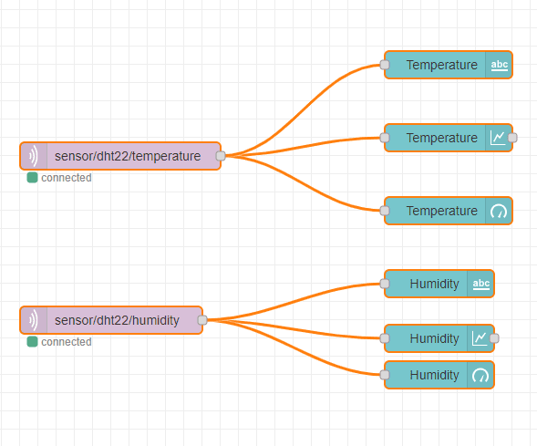
The image above shows our Node-Red flow that will display our Arduino sensor readings thru MQTT. It uses the module node-red-dashboard to display the sensor readings in both text and graphical charts that automatically update themselves asynchronously.
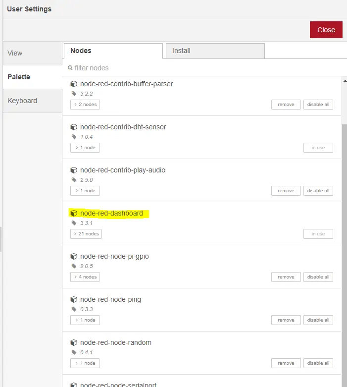
Install the library by going to the Manage Palette and searching for the “node-red-dashboard” if you have not done so.
This flow is also available on my GitHub repository for you to check and is also shown below.
[{"id":"0b958bf98108ac7c","type":"ui_chart","z":"d4f46a5a0a4d81d6","name":"","group":"90ca17ebd42f9ffa","order":5,"width":11,"height":6,"label":"Temperature","chartType":"line","legend":"false","xformat":"HH:mm:ss","interpolate":"linear","nodata":"","dot":false,"ymin":"0","ymax":"50","removeOlder":1,"removeOlderPoints":"","removeOlderUnit":"3600","cutout":0,"useOneColor":false,"useUTC":false,"colors":["#1f77b4","#aec7e8","#ff7f0e","#2ca02c","#98df8a","#d62728","#ff9896","#9467bd","#c5b0d5"],"outputs":1,"useDifferentColor":false,"className":"","x":690,"y":260,"wires":[[]]},{"id":"1935c2e04eeb79dc","type":"ui_chart","z":"d4f46a5a0a4d81d6","name":"","group":"90ca17ebd42f9ffa","order":8,"width":11,"height":6,"label":"Humidity","chartType":"line","legend":"false","xformat":"HH:mm:ss","interpolate":"linear","nodata":"","dot":false,"ymin":"0","ymax":"100","removeOlder":1,"removeOlderPoints":"","removeOlderUnit":"3600","cutout":0,"useOneColor":false,"useUTC":false,"colors":["#1f77b4","#aec7e8","#ff7f0e","#2ca02c","#98df8a","#d62728","#ff9896","#9467bd","#c5b0d5"],"outputs":1,"useDifferentColor":false,"className":"","x":680,"y":480,"wires":[[]]},{"id":"076194cdb1d2a526","type":"ui_gauge","z":"d4f46a5a0a4d81d6","name":"","group":"90ca17ebd42f9ffa","order":6,"width":5,"height":5,"gtype":"gage","title":"Temperature","label":"Celcius","format":"{{value}}","min":0,"max":"50","colors":["#00b500","#e6e600","#ca3838"],"seg1":"","seg2":"","diff":false,"className":"","x":690,"y":340,"wires":[]},{"id":"056796718e758a6b","type":"ui_gauge","z":"d4f46a5a0a4d81d6","name":"","group":"90ca17ebd42f9ffa","order":10,"width":5,"height":5,"gtype":"gage","title":"Humidity","label":"%","format":"{{value}}","min":0,"max":"100","colors":["#00b500","#e6e600","#ca3838"],"seg1":"","seg2":"","diff":false,"className":"","x":680,"y":520,"wires":[]},{"id":"2ef004bee1e74e95","type":"mqtt in","z":"d4f46a5a0a4d81d6","name":"","topic":"sensor/dht22/temperature","qos":"0","datatype":"utf8","broker":"abf7235cc1485ab2","nl":false,"rap":true,"rh":0,"inputs":0,"x":330,"y":280,"wires":[["0b958bf98108ac7c","076194cdb1d2a526","0c24b89fd0c850bd"]]},{"id":"e6fc867230945246","type":"mqtt in","z":"d4f46a5a0a4d81d6","name":"","topic":"sensor/dht22/humidity","qos":"0","datatype":"auto-detect","broker":"abf7235cc1485ab2","nl":false,"rap":true,"rh":0,"inputs":0,"x":320,"y":460,"wires":[["1935c2e04eeb79dc","056796718e758a6b","6f9b868542396b05"]]},{"id":"0c24b89fd0c850bd","type":"ui_text","z":"d4f46a5a0a4d81d6","group":"90ca17ebd42f9ffa","order":1,"width":6,"height":1,"name":"","label":"Temperature","format":"{{msg.payload}}","layout":"col-center","className":"","x":690,"y":180,"wires":[]},{"id":"6f9b868542396b05","type":"ui_text","z":"d4f46a5a0a4d81d6","group":"90ca17ebd42f9ffa","order":3,"width":6,"height":1,"name":"","label":"Humidity","format":"{{msg.payload}}","layout":"col-center","className":"","x":680,"y":420,"wires":[]},{"id":"90ca17ebd42f9ffa","type":"ui_group","name":"DHT22","tab":"451ab0586fb55eb3","order":1,"disp":true,"width":"16","collapse":false,"className":""},{"id":"abf7235cc1485ab2","type":"mqtt-broker","name":"Local Mosquitto Broker","broker":"192.168.100.22","port":"1883","clientid":"","autoConnect":true,"usetls":false,"protocolVersion":"4","keepalive":"60","cleansession":true,"birthTopic":"","birthQos":"0","birthPayload":"","birthMsg":{},"closeTopic":"","closeQos":"0","closePayload":"","closeMsg":{},"willTopic":"","willQos":"0","willPayload":"","willMsg":{},"userProps":"","sessionExpiry":""},{"id":"451ab0586fb55eb3","type":"ui_tab","name":"Custom Dashboard","icon":"dashboard","order":1,"disabled":false,"hidden":false}]Let’s go through how each node is configured. The temperature and humidity displays are almost similar and they are using the same set of nodes so we will only be looking at the temperature.
MQTT In Node
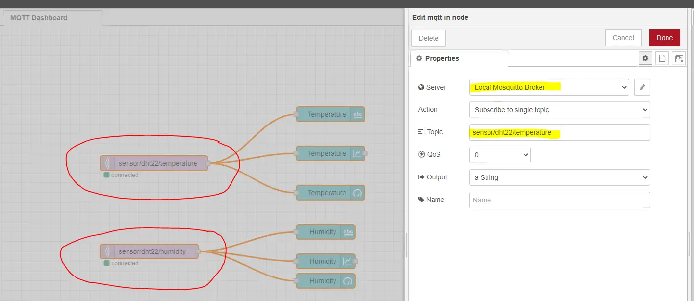
The MQTT In Node is configured to listen to my Mosquitto MQTT broker and I have set the topic to sensor/dht22/temperature. For the humidity, this is set to sensor/dht22/humidity and this should match the Arduino code.
Text Node
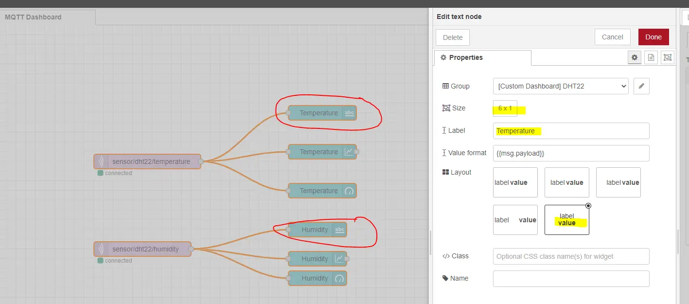
The text node is configured to display the DHT22 sensor readings for both temperature and humidity.
Chart Node
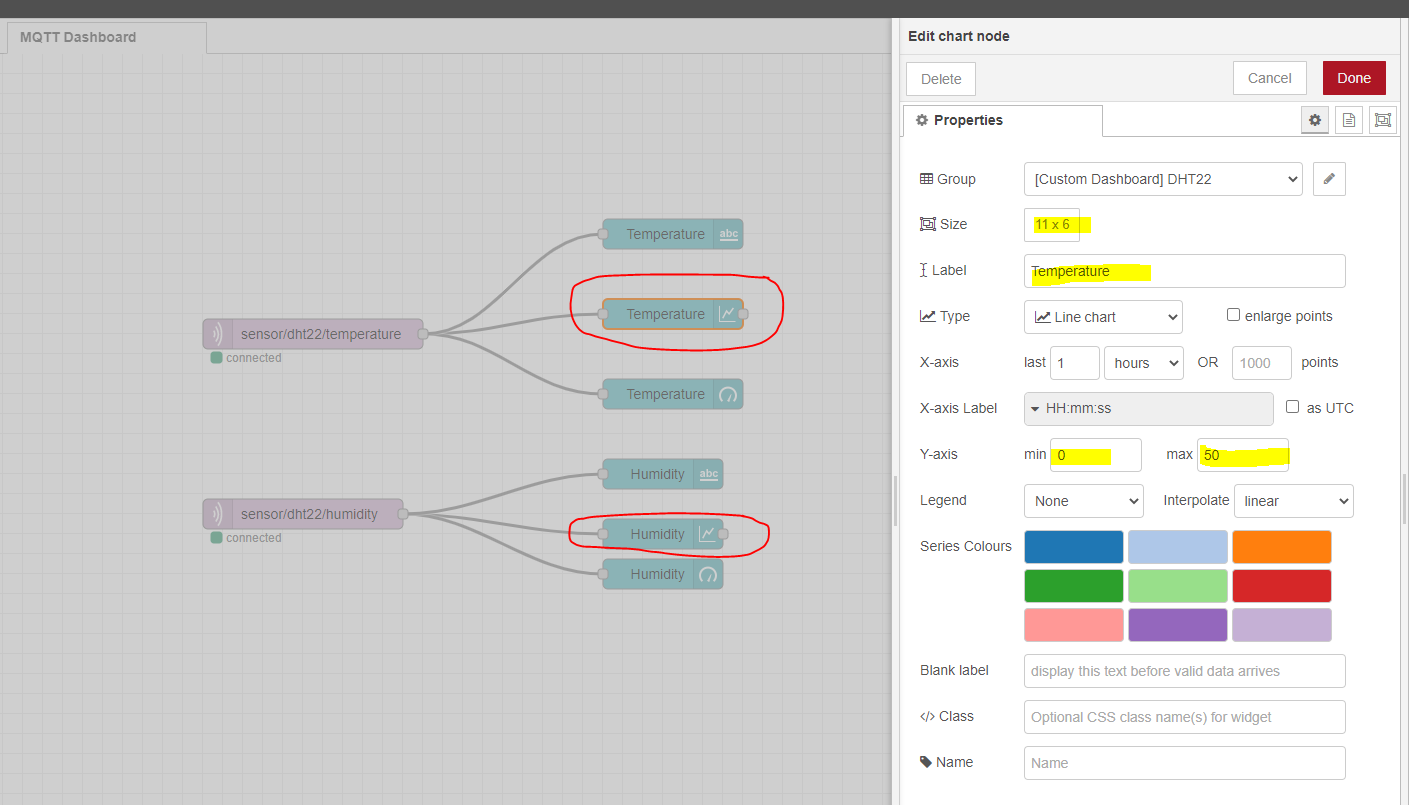
To display the historical chart then we would need the Chart node with the following configurations.
Gauge Node
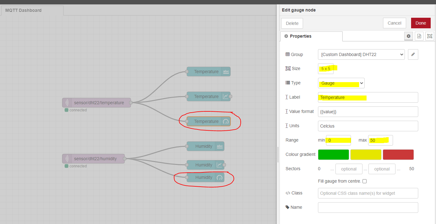
The Gauge Node is configured with the following information.
The text, chart, and gauge node receives all its data from the MQTT In node which listens to the topics configured to it. When the MQTT broker sends the message then the MQTT In node is sending the payload to display it automatically.
That is all for the Node-Red code and as you can see I did not add any custom code but just drag the Node-Red dashboard nodes and wire them together.
How to adjust the Layout in Node-Red Dashboard?
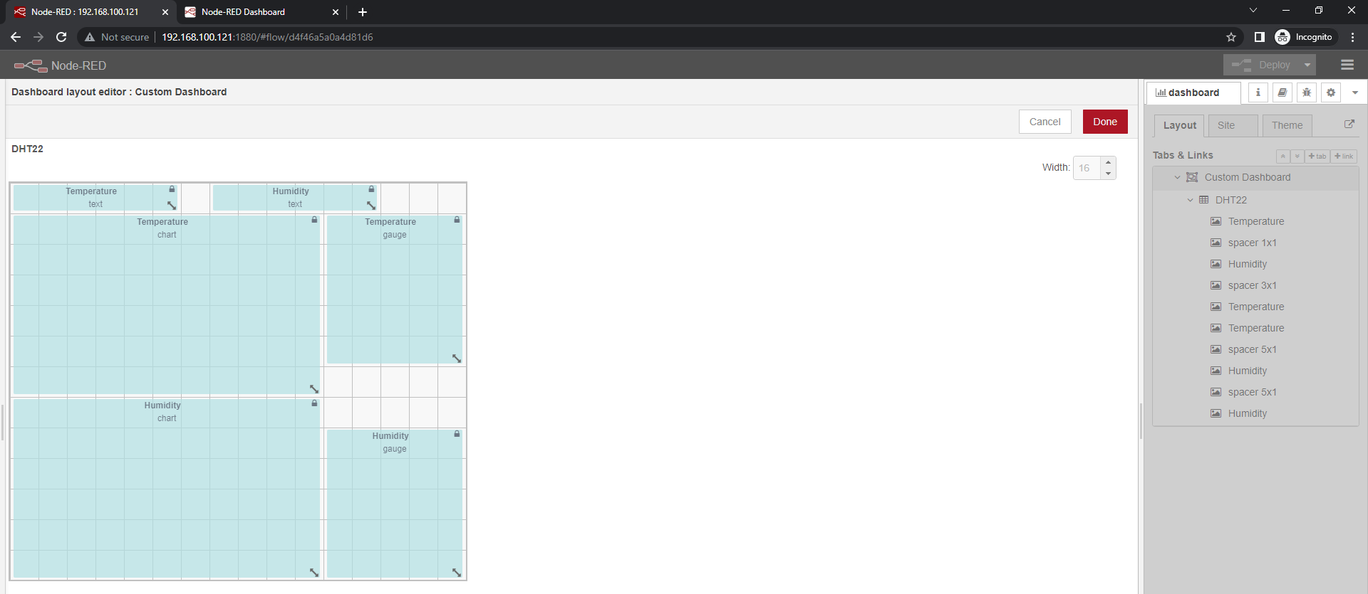
If you want to alter the layout then go to the Dashboard Layout Editor and change how the following nodes are arranged.
Wrap Up
We have successfully displayed the Arduino sensor readings in our Node-Red IoT dashboard without programming any HTML/CSS/Javascript code in this post. Using node-red-dashboard greatly simplifies the creation of a user interface.
I hope you learned something! Happy Exploring!
Leave a Reply