Introduction
Do you need to control your MicroPython-based Internet of Things (IoT) projects from your browser or your mobile phone then creating a web server will do the job. This post will show how to configure your Raspberry Pi Pico W with a web server to control your hardware components in real-time.
If you want to see this project in video format then please see below or watch it on my YouTube channel.
What are we building?
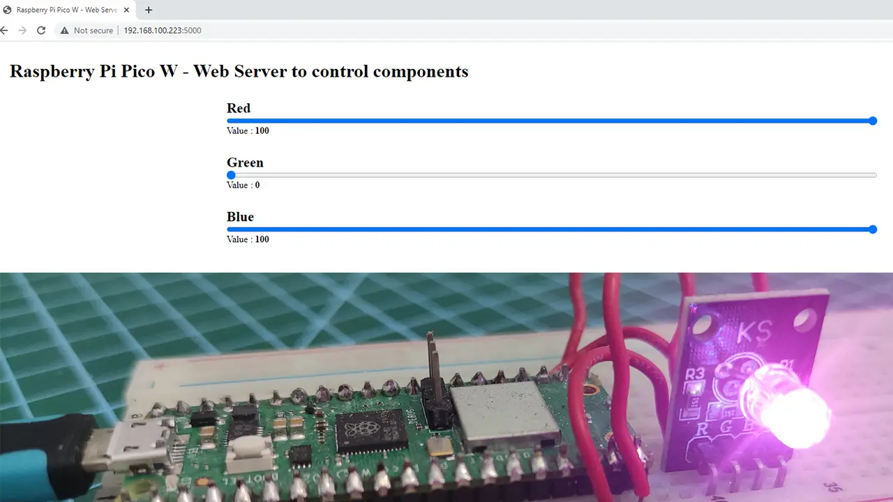
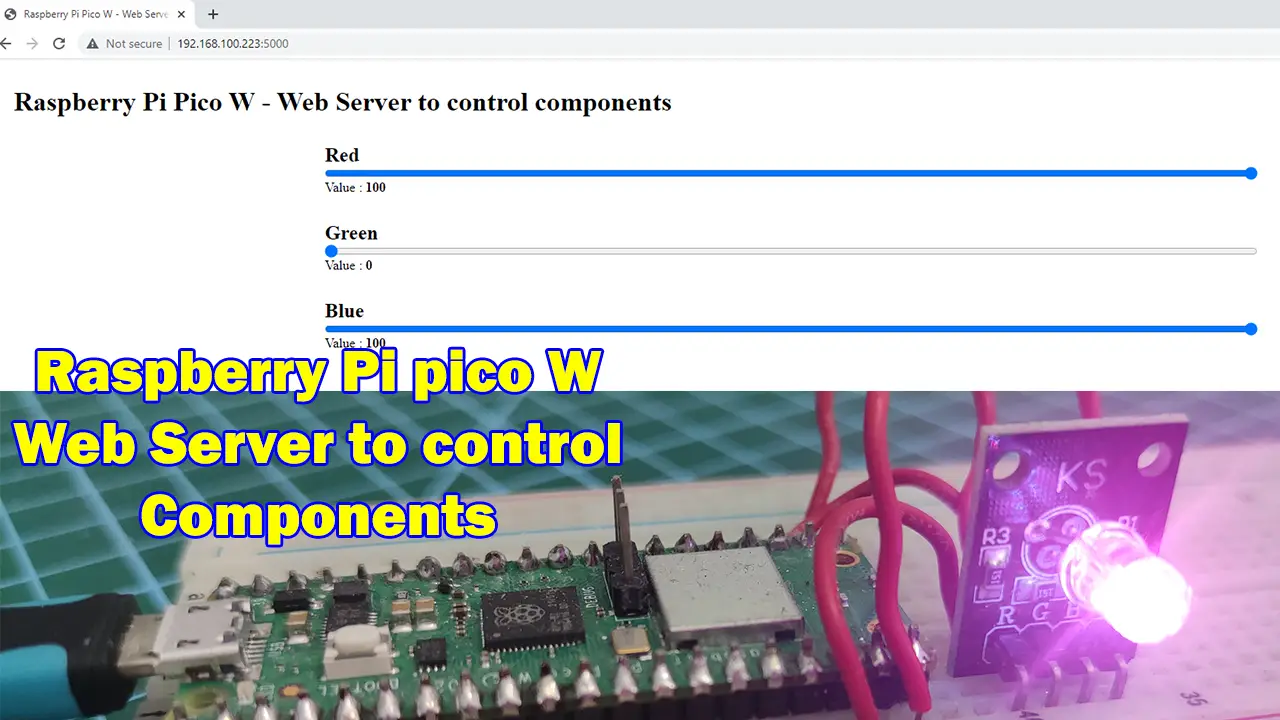
We are going to build a web application that will control the color displayed by our RGB(Red-Green-Blue) module by using the slider above. Whenever the slider is being slid for each RGB combination then the RGB module should display it in real-time.
Design
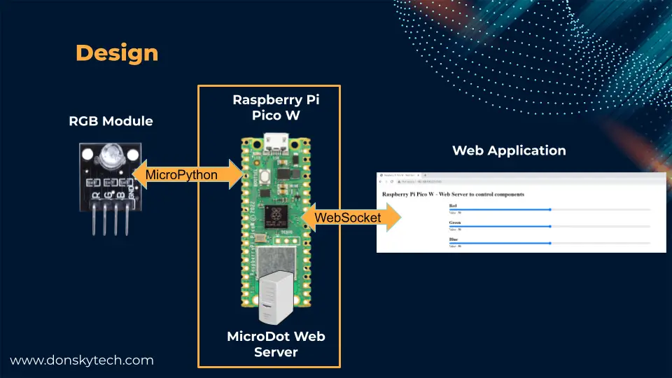
The image above is how this project is designed wherein the Raspberry Pi Pico W is configured with a web server. The web server creates the web application that will control our RGB module. However, you can use any other components here such as a servo motor, an I2C LCD, or any other components that you want.
We are using WebSocket in this project as we need a real-time response between our web application and our RGB module. On the other hand, if you are not familiar with what WebSocket is then please see the below posts.
Related Content:
Using WebSocket in the Internet of Things (IoT) projects
Using WebSocket in MicroPython – A Practical Example
Prerequisites
Download the latest firmware for your Raspberry Pi Pico W device.
Related Content:
How to Install MicroPython firmware on Raspberry Pi Pico?
You should be familiar with how to use the MicroPython library called MicroDot that we will use in creating the web server of our project as I won’t be discussing so much on how this library works. If this is the first time you have heard of this library then please see the following posts I have created to get you started.
Related Content:
Develop MicroPython Application using MicroDot
How to create a MicroPython Web Server the easy way!
I have used Thonny IDE in developing this project but you can use any other IDE that you are familiar with.
Related Content:
MicroPython Development Using Thonny IDE
How to guides in Thonny IDE using MicroPython
Parts/Components Required
The followings are the components needed to follow along with this post.
- Raspberry Pi Pico W – Amazon | AliExpress | Bangood
- RGB Module – Amazon | AliExpress | Bangood
- Breadboard – Amazon | AliExpress | Bangood
- Connecting Wires – Amazon | AliExpress | Bangood
Disclosure: These are affiliate links and I will earn small commissions to support my site when you buy through these links.
Wiring/Schematic
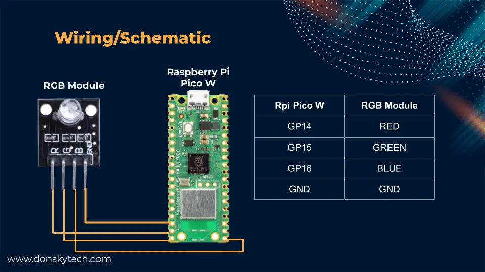
The image above shows the wiring/schematic for this project.
Code
The complete code for this MicroPython project where we will control our components in a web server is available in my GitHub repository and you can either download it as a zip file or clone it using the below Git command.
git clone https://github.com/donskytech/micropython-raspberry-pi-pico.git
cd control-components-from-web-server
Once the download is finished then open the project files in Thonny IDE. The below image shows the different files included in our project.
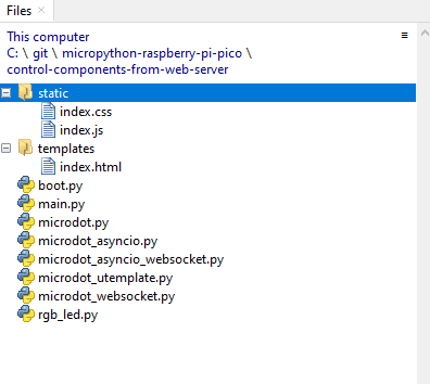
- boot.py – we used this to connect to our WiFi network
- main.py – contains our MicroDot web server
- rgb_led.py – our interface to our RGB LED module
- static/index.css and static/index.js – the CSS (Cascading Stylesheets) and javascript file used to send WebSocket messages from our browser into our Raspberry Pi Pico W MicroDot web server.
- microdot* – these are MicroDot-specific files that I have just copied from the project source files.
Let us go over what each line of the file does.
boot.py
# boot.py -- run on boot-up
import network

# Replace the following with your WIFI Credentials
SSID = "<CHANGE_ME>"
SSI_PASSWORD = "<CHANGE_ME>"

def do_connect():
    import network
    sta_if = network.WLAN(network.STA_IF)
    if not sta_if.isconnected():
        print('connecting to network...')
        sta_if.active(True)
        sta_if.connect(SSID, SSI_PASSWORD)
        while not sta_if.isconnected():
            pass
    print('Connected! Network config:', sta_if.ifconfig())

print("Connecting to your wifi...")
do_connect()
We used this file to connect to our WiFi network so we get assigned an IP Address. Make sure to change the SSID and SSI_PASSWORD to match your network configuration credentials.
rgb_led.py
import time
from machine import Pin,PWM

#RGB
RED = 0
GREEN = 1
BLUE = 2

RED_COLOR = "red"
GREEN_COLOR = "green"
BLUE_COLOR = "blue"

# Class that wil interface with our RGB Module
class RGBLEDModule:
    def __init__(self, pwm_pins):
        self.pwms = [PWM(Pin(pwm_pins[RED])),PWM(Pin(pwm_pins[GREEN])),
                PWM(Pin(pwm_pins[BLUE]))]
        self.init_pwms()

    # Initialize PWM Pins
    def init_pwms(self):
        for pwm in self.pwms:
            pwm.freq(1000)

    # Deinitialize PWM fins
    def deinit_pwms(self):
        self.turn_off_rgb()
        for pwm in self.pwms:
            pwm.deinit()

    # Map RGB values from 0-100 to duty cycle 0-65535
    def map_range(self, x, in_min, in_max, out_min, out_max):
      return (x - in_min) * (out_max - out_min) // (in_max - in_min) + out_min

    # Turn off RGB
    def turn_off_rgb(self):
        self.pwms[RED].duty_u16(0)
        self.pwms[GREEN].duty_u16(0)
        self.pwms[BLUE].duty_u16(0)
        time.sleep(0.01)

    # Set RGB Color
    def set_rgb_color(self, rgb_color):
        self.turn_off_rgb()


        self.pwms[RED].duty_u16(self.map_range(int(rgb_color[RED_COLOR]), 0, 100, 0, 65535))
        self.pwms[GREEN].duty_u16(self.map_range(int(rgb_color[GREEN_COLOR]), 0, 100, 0, 65535))
        self.pwms[BLUE].duty_u16(self.map_range(int(rgb_color[BLUE_COLOR]), 0, 100, 0, 65535))
This file is how we would interface with our RGB LED module. Let us go over what each line of the code does.
import time
from machine import Pin,PWM

#RGB
RED = 0
GREEN = 1
BLUE = 2

RED_COLOR = "red"
GREEN_COLOR = "green"
BLUE_COLOR = "blue"
We import the necessary classes to communicate with our RGB module and define several constants that we will be using in the code later.
# Class that wil interface with our RGB Module
class RGBLEDModule:
    def __init__(self, pwm_pins):
        self.pwms = [PWM(Pin(pwm_pins[RED])),PWM(Pin(pwm_pins[GREEN])),
                PWM(Pin(pwm_pins[BLUE]))]
        self.init_pwms()

    # Initialize PWM Pins
    def init_pwms(self):
        for pwm in self.pwms:
            pwm.freq(1000)

    # Deinitialize PWM fins
    def deinit_pwms(self):
        self.turn_off_rgb()
        for pwm in self.pwms:
            pwm.deinit()
Next, we created a class named RGBLEDModule which would represent our interface to our hardware component which is the RGB LED module. The class constructor requires the PWM pins where the RGB LED is connected.
On the other hand, init_pwms() and deinit_pwms() are used to set and de-set the PWM (Pulse Width Modulation) configuration for our RGB Module.
 # Map RGB values from 0-100 to duty cycle 0-65535
    def map_range(self, x, in_min, in_max, out_min, out_max):
      return (x - in_min) * (out_max - out_min) // (in_max - in_min) + out_min

    # Turn off RGB
    def turn_off_rgb(self):
        self.pwms[RED].duty_u16(0)
        self.pwms[GREEN].duty_u16(0)
        self.pwms[BLUE].duty_u16(0)
        time.sleep(0.01)

    # Set RGB Color
    def set_rgb_color(self, rgb_color):
        self.turn_off_rgb()


        self.pwms[RED].duty_u16(self.map_range(int(rgb_color[RED_COLOR]), 0, 100, 0, 65535))
        self.pwms[GREEN].duty_u16(self.map_range(int(rgb_color[GREEN_COLOR]), 0, 100, 0, 65535))
        self.pwms[BLUE].duty_u16(self.map_range(int(rgb_color[BLUE_COLOR]), 0, 100, 0, 65535))
We define a function map_range() whose job is to map the value coming from our web browser (0-100) into the values understood by our PWM pins duty cycle which are from 0-65535.
The functionturn_off_rgb() is needed to temporarily black out RGB LED whenever we try to set a new color. Lastly, the function set_rgb_color() is used to set the duty cycle for each PWM pin and it is expecting a Python dictionary object that will contain the values for the RGB. An example dictionary input is shown below wherein we are setting the duty cycle to 50% of its values.
rgb_led.set_rgb_color({'blue': '50', 'red': '50', 'green': '50'})main.py
from microdot_asyncio import Microdot, Response, send_file
from microdot_utemplate import render_template
from microdot_asyncio_websocket import with_websocket
from rgb_led import RGBLEDModule
import time
import ujson

# initialize RGB
pwm_pins = [14, 15, 16]
rgb_led = RGBLEDModule(pwm_pins)
# Set default color to 50% each for RGB
rgb_led.set_rgb_color({'blue': '50', 'red': '50', 'green': '50'})

# Initialize MicroDot
app = Microdot()
Response.default_content_type = 'text/html'

# root route
@app.route('/')
async def index(request):
    return render_template('index.html')

# initialize websocket
@app.route('/ws')
@with_websocket
async def read_sensor(request, ws):
    while True:
        data = await ws.receive()
        rgb_color = ujson.loads(data)
        rgb_led.set_rgb_color(rgb_color)
        await ws.send("OK")

# Static CSS/JSS
@app.route("/static/<path:path>")
def static(request, path):
    if ".." in path:
        # directory traversal is not allowed
        return "Not found", 404
    return send_file("static/" + path)


# shutdown
@app.get('/shutdown')
def shutdown(request):
    request.app.shutdown()
    return 'The server is shutting down...'


if __name__ == "__main__":
    try:
        app.run()
    except KeyboardInterrupt:
        rgb_led.deinit_pwms()
        pass
This is the most important file in our project and it does several things such as the creation of the MicroDot web server, the handling of the WebSocket message exchange, and controlling the color of the RGB LED module.
from microdot_asyncio import Microdot, Response, send_file
from microdot_utemplate import render_template
from microdot_asyncio_websocket import with_websocket
from rgb_led import RGBLEDModule
import time
import ujson
First, we import the necessary classes to create our MicroDot web server, and the class RGBLEDModule that we will be needing to control our RGB LED component.
# initialize RGB
pwm_pins = [14, 15, 16]
rgb_led = RGBLEDModule(pwm_pins)
# Set default color to 50% each for RGB
rgb_led.set_rgb_color({'blue': '50', 'red': '50', 'green': '50'})
Next, we define our PWM Pins where we have connected the pins of our and create an instance of the class RGBLEDModule. We initially set the color of the RGB LED at 50% of each Red, Green, and Blue LED.
# Initialize MicroDot
app = Microdot()
Response.default_content_type = 'text/html'

# root route
@app.route('/')
async def index(request):
    return render_template('index.html')
Here, we have defined our MicroDot web server and defined our root route that will serve our index.html.
# initialize websocket
@app.route('/ws')
@with_websocket
async def read_sensor(request, ws):
    while True:
        data = await ws.receive()
        rgb_color = ujson.loads(data)
        rgb_led.set_rgb_color(rgb_color)
        await ws.send("OK")
This is where we defined our WebSocket route with the path “/ws” and this function will wait for any WebSocket messages coming from our browser. If a WebSocket message is received then we convert it into a Python dictionary object and call our function set_rgb_color() which will set the color of the RGB LED module. After which, we reply back with an “OK” string to the browser.
# Static CSS/JSS
@app.route("/static/<path:path>")
def static(request, path):
    if ".." in path:
        # directory traversal is not allowed
        return "Not found", 404
    return send_file("static/" + path)


# shutdown
@app.get('/shutdown')
def shutdown(request):
    request.app.shutdown()
    return 'The server is shutting down...'
The function static() is used to serve static files such as our CSS and Javascript files to our browser while the function shutdown is used to shut down our MicroDot web server.
if __name__ == "__main__":
    try:
        app.run()
    except KeyboardInterrupt:
        rgb_led.deinit_pwms()
        pass
The code above is the entry point of our project. We also capture the KeyboardInterrupt exception so that we could deinitialize our PWM pins when we exit the application.
templates/index.html
<!DOCTYPE html>
<html lang="en">
  <head>
    <meta charset="UTF-8" />
    <meta name="viewport" content="width=device-width, initial-scale=1.0" />
    <meta http-equiv="X-UA-Compatible" content="ie=edge" />
    <title>Raspberry Pi Pico W - Web Server to control components</title>
    <link rel="stylesheet" href="/static/index.css" />
  </head>
  <body>
   <main>
      <h1>Raspberry Pi Pico W - Web Server to control components</h1>
      <div class="container">
        <div class="slidecontainer">
          <label for="redSlider" class="color-label">Red</label>
          <input
            type="range"
            min="0"
            max="100"
            value="50"
            class="slider"
            id="redSlider"
          />
          <div>
            <label>Value : </label>
            <b id="redValue">50</b>
          </div>
        </div>
        <div class="slidecontainer">
          <label for="redSlider" class="color-label">Green</label>
          <input
            type="range"
            min="0"
            max="100"
            value="50"
            class="slider"
            id="greenSlider"
          />
          <div>
            <label>Value : </label>
            <b id="greenValue">50</b>
          </div>
        </div>
        <div class="slidecontainer">
          <label for="redSlider" class="color-label">Blue</label>
          <input
            type="range"
            min="0"
            max="100"
            value="50"
            class="slider"
            id="blueSlider"
          />
          <div>
            <label>Value : </label>
            <b id="blueValue">50</b>
          </div>
        </div>
      </div>
    </main>
    <script src="/static/index.js"></script>
  </body>
</html>
This is our main HTML file that will show the slider widget that we will use to control the color of our RGB LED module.
static/index.js
// Slider
var redSlider = document.querySelector("#redSlider");
var redValue = document.querySelector("#redValue");

var greenSlider = document.querySelector("#greenSlider");
var greenValue = document.querySelector("#greenValue");

var blueSlider = document.querySelector("#blueSlider");
var blueValue = document.querySelector("#blueValue");

redSlider.addEventListener("change", () => {
  redValue.textContent = redSlider.value;
  sendMessage(
    JSON.stringify({
      red: redSlider.value,
      green: greenSlider.value,
      blue: blueSlider.value,
    })
  );
});

greenSlider.addEventListener("change", () => {
  greenValue.textContent = greenSlider.value;
  sendMessage(
    JSON.stringify({
      red: redSlider.value,
      green: greenSlider.value,
      blue: blueSlider.value,
    })
  );
});

blueSlider.addEventListener("change", () => {
  blueValue.textContent = blueSlider.value;
  sendMessage(
    JSON.stringify({
      red: redSlider.value,
      green: greenSlider.value,
      blue: blueSlider.value,
    })
  );
});

// WebSocket support
var targetUrl = `ws://${location.host}/ws`;
var websocket;
window.addEventListener("load", onLoad);

function onLoad() {
  initializeSocket();
}

function initializeSocket() {
  console.log("Opening WebSocket connection MicroPython Server...");
  websocket = new WebSocket(targetUrl);
  websocket.onopen = onOpen;
  websocket.onclose = onClose;
  websocket.onmessage = onMessage;
}
function onOpen(event) {
  console.log("Starting connection to WebSocket server..");
}
function onClose(event) {
  console.log("Closing connection to server..");
  setTimeout(initializeSocket, 2000);
}
function onMessage(event) {
  console.log("WebSocket message received:", event);
}

function sendMessage(message) {
  websocket.send(message);
}
This is the file that will send the WebSocket messages to our MicroDot web server and capture the values from our slider.
// Slider
var redSlider = document.querySelector("#redSlider");
var redValue = document.querySelector("#redValue");

var greenSlider = document.querySelector("#greenSlider");
var greenValue = document.querySelector("#greenValue");

var blueSlider = document.querySelector("#blueSlider");
var blueValue = document.querySelector("#blueValue");
These are variables that refer to our HTML Slider components that we will use later in getting the values.
redSlider.addEventListener("change", () => {
  redValue.textContent = redSlider.value;
  sendMessage(
    JSON.stringify({
      red: redSlider.value,
      green: greenSlider.value,
      blue: blueSlider.value,
    })
  );
});

greenSlider.addEventListener("change", () => {
  greenValue.textContent = greenSlider.value;
  sendMessage(
    JSON.stringify({
      red: redSlider.value,
      green: greenSlider.value,
      blue: blueSlider.value,
    })
  );
});

blueSlider.addEventListener("change", () => {
  blueValue.textContent = blueSlider.value;
  sendMessage(
    JSON.stringify({
      red: redSlider.value,
      green: greenSlider.value,
      blue: blueSlider.value,
    })
  );
});
The three functions above are identical and whose function is to display the current value of each slider. At the same time, we use these functions to send a WebSocket message to our web server. We format the message as a JSON string prior to sending it to our web server. Whenever we slide our sliders then a change event is raised and we use this event to send the current values of each slider.
// WebSocket support
var targetUrl = `ws://${location.host}/ws`;
var websocket;
window.addEventListener("load", onLoad);

function onLoad() {
  initializeSocket();
}

function initializeSocket() {
  console.log("Opening WebSocket connection MicroPython Server...");
  websocket = new WebSocket(targetUrl);
  websocket.onopen = onOpen;
  websocket.onclose = onClose;
  websocket.onmessage = onMessage;
}
function onOpen(event) {
  console.log("Starting connection to WebSocket server..");
}
function onClose(event) {
  console.log("Closing connection to server..");
  setTimeout(initializeSocket, 2000);
}
function onMessage(event) {
  console.log("WebSocket message received:", event);
}

function sendMessage(message) {
  websocket.send(message);
}
This is where we open our WebSocket connection to our MicroDot web server. The sendMessage(message) function is the function we used to send the actual WebSocket message.
static/index.css
* {
  margin: 0;
  padding: 0;
  outline: 0;
}
main {
  padding: 2rem;
}
.container {
  display: flex;
  flex-flow: column nowrap;
  align-items: center;
}
.slidecontainer {
  display: flex;
  flex-flow: column nowrap;
  width: 60%;
  margin-top: 2rem;
}
.color-label {
  font-size: 1.5rem;
  font-weight: bold;
}
These are basic CSS stylesheet classes that we use to apply a little bit of styling to our web page.
microdot*
These are MicroDot-specific files that I have just copied from the project source files.
How to run the project?
If you want to run this project then you first need to install the template library in your Raspberry Pi Pico W. If you are unsure how this is done then follow this How to install MicroPython libraries or packages in Thonny IDE?
Next, upload all the files into your Raspberry Pi Pico W file system. Make sure that you have changed the boot.py to match your network configuration.
Lastly, access the following URL from your browser.
http://<IP-Address>:5000Wrap Up
We have successfully set up our Raspberry Pi Pico W with a web server that can control our electronic components from our browser. In addition, I have shown you how you can get a real-time response from your electronic components by using WebSocket.
I hope you learned something! Happy Exploring!
Read Next:
Pico W -MicroPython MQTT – BMP/BME 280 Weather Station
Control DS18B20 using MicroPython with a Weather Station Project
Leave a Reply