Introduction
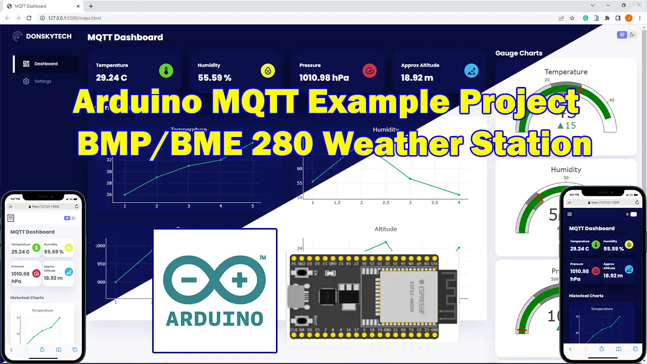
In this tutorial, I am going to share with you my Arduino MQTT example project that uses BMP/BME 280 sensor to display its sensor readings. We are going to publish MQTT messages to our broker using our ESP32/ESP8266 microcontroller boards and display the sensor readings in a custom dashboard that will show it in both text and graphical chart format.
If you want to see this project in a video format then please see below. You can also watch this on my YouTube channel.
Design
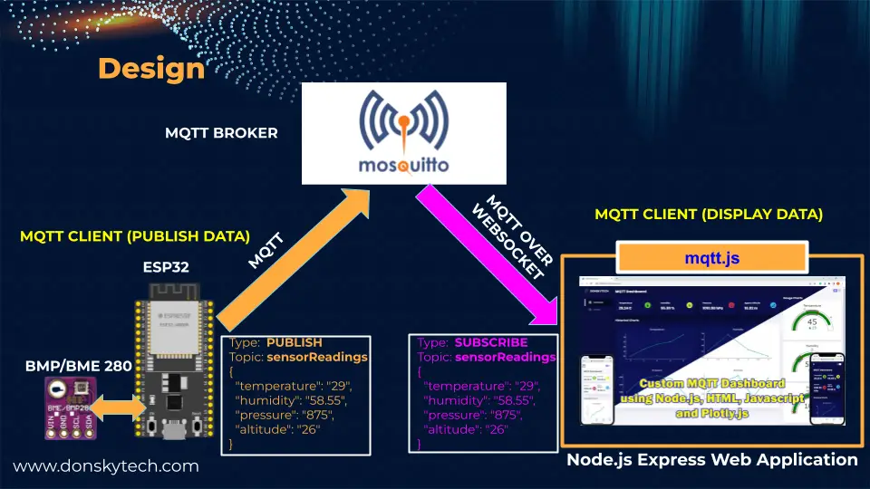
The image above is how the overall message flows between the different components in our system. There are three major components in this Arduino MQTT BMP/BME280 Weather station example project and they are listed below.
- MQTT Broker – the Mosquitto broker acts as our middleman in the message exchange. It is the one that facilitates the processing of incoming MQTT messages and delivers it to interested receivers.
- ESP32/ESP8266 and the BMP/BME 280 – this is the MQTT client that is the source of our information (publisher). The ESP32/ESP8266 published the sensor readings as MQTT messages to our broker using the topic “sensorReadings” and inside it is a message that contains the readings from our BMP/BME280 sensor. This application was built using the Arduino framework using Visual Studio Code and PlatformIO IDE extension.
- Dashboard – The dashboard application acts as another MQTT client (subscriber) to our MQTT broker and is subscribed to the same MQTT topic “sensorReadings“. It displays the MQTT messages as text and colorful graphs for better usability. This application was built using Node.js, HTML/CSS/Javascript, and the mqtt.js library.
With the publish/subscribe model of MQTT then it is possible for us to separately code the part that publishes the sensor readings on a particular topic and create our own dashboard that subscribes to the same topic and display its readings. All the clients connected to our MQTT broker do not need to know each other making this setup very much ideal for the Internet of Things (IoT) projects.
Why build your own MQTT Dashboard?
I just think it’s fun creating your own dashboard to display your MQTT data especially if you are running your own local instance of an MQTT broker like the Mosquitto in your own Internet of Things (IoT) project like your own Home Automation system. You have options to use popular cloud MQTT brokers which contain built-in support for displaying MQTT data but that would be the subject of another post. Another option is to use the popular tool called Node-Red but we will get to that later also.
Why use MQTT over HTTP?
The popular question you might ask is, “why not just communicate directly with the ESP32/ESP8266 thru HTTP(Hypertext Transfer Protocol) and remove the middleman (MQTT broker) from the equation?”.
If you have been an avid reader of my blog post then you might be familiar with my earlier post about Using Arduino with BME280 plus a weather station project wherein we used the same ESP32/ESP8266 MCU board as a web server that will be the source of our information and we are able to retrieve the BMP/BME280 sensor readings as both text and graph chart also. However, if you are a keen observer then you would notice that we developed everything inside the ESP32/ESP8266 board. There are performance limits if we do this as the microcontroller boards have both limited memory and space.
HTTP is much heavier than MQTT in terms of the use of network bandwidth after all MQTT protocol was developed for this purpose. If we have multiple users accessing our ESP32/ESP8266 MicroController board then we cannot add more memory to our MCU boards to service the incoming requests. Also, the Arduino framework was not specifically designed to display and service web application requests. There are excellent tools like Node.js, Express, or even React.js for the purpose of developing web applications.
Lastly, I personally think that many of the users of MQTT will now work in the browser as more users are using their mobile devices more and more. Fortunately, our browser can now support the MQTT message exchange thru WebSocket.
Why use WebSocket over MQTT?
If you take a look at my design diagram above then you might have noticed that the messages are delivered thru MQTT over WebSocket.
Browsers by default cannot communicate with our MQTT broker so we need to wrap the MQTT packet inside a WebSocket envelope. If you are not familiar with what WebSocket is and how MQTT over WebSocket works then please see my post about it earlier.
Related Content:
Using WebSocket in the Internet of Things (IoT) projects
Publish and Subscribe MQTT messages over WebSocket
Now that is a bird’s eye view of the “lousy” design part of this project and I know you would like to know how this project works in code. 🙂
Components/Parts Required
The following are the needed components/parts to be able to follow along with this post.
- ESP32 – Amazon | AliExpress | Bangood
- or ESP8266 – Amazon | AliExpress | Bangood
- BME280/BMP280 – Amazon | AliExpress
- Breadboard – Amazon | AliExpress | Bangood
- Connecting Wires – Amazon | AliExpress | Bangood
Disclosure: These are affiliate links and I will earn small commissions to support my site when you buy through these links.
Prerequisites
You will need an MQTT broker that you are able to connect with WebSocket enabled. I have used Mosquitto in developing this post. You also need to be familiar with the basics of MQTT and how you can use it in your Arduino program. Please refer to the earlier post I have written if you are not familiar with this before proceeding further.
Related Content:
Install Mosquitto MQTT Windows
MQTT Tutorial using Arduino Framework
I have used Visual Studio Code with the PlatformIO IDE extension installed while working on this project but the code is applicable even when using the Arduino IDE.
Related Content:
PlatformIO Tutorial for Arduino Development
Install Visual Studio Code or VSCode on Windows
Wiring/Schematic
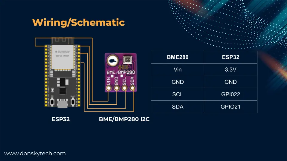
The above image shows the wiring and schematic of our ESP32/ESP8266 Arduino-based MQTT example project. I am using the I2C module of the BMP/BME 280 sensor so I am needing only the 4 pins. If you are not familiar with how BMP/BME 280 sensor works with Arduino then please read through my earlier post about it below.
Related Content:
Using Arduino with BME280 plus a weather station project
Code
As mentioned in the Design section, we need to discuss two lines of code for this Arduino MQTT example weather station dashboard project.
- Custom MQTT Dashboard created using Node.js, HTML, CSS, and Javascript
- ESP32/ESP8266 MQTT Arduino program
Custom MQTT Dashboard created using Node.js, HTML, CSS, and Javascript
I have discussed extensively this project in my earlier post about How to build your own custom MQTT dashboard? This project requires some familiarity with Node.js, Express, and the use of mqtt.js.
Related Content:
MQTT using Node.js with practical examples
I suggest you scan through the explanation there on how this project works but if you would like to run this project then follow the steps outlined in my GitHub repository or follow the steps below. You should have installed Node.js runtime in your environment prior to running these steps and have Git.
Related Content:
Install Node.js on Windows
Clone the repository.
git clone https://github.com/donskytech/mqtt-custom-dashboard-node-js.git
cd mqtt-custom-dashboard-node-js
Rename the .env.local to .env and edit the .env and set the MQTT broker URL to the MQTT broker that you are using. If you are using a locally-hosted Mosquitto MQTT broker then this should point to the IP Address where you installed it. This is my current .env configuration setup.
NAME=DONSKYTECH
DASHBOARD_TITLE=MQTT ARDUINO BME280 WEATHER STATION DASHBOARD
MQTT_BROKER=ws://192.168.100.22:9001/mqtt
MQTT_TOPIC=sensorReadings
Install the dependencies and run the project.
npm install && npm run devIf everything is okay then open your browser and type in the following URL. This should open up our custom MQTT dashboard with blank values.
http://localhost:3000ESP32/ESP8266 MQTT Arduino program
The complete code for our Arduino MQTT example project that will publish the sensor readings from our BME/BMP 280 sensor can be found in my GitHub repository and it is shown below.
You can either download the program as a zip file or clone it using the below command.
git clone https://github.com/donskytech/mqtt-arduino-bme280.gitLibraries used
The libraries used by this project are the following which you can find also in the platform.ini file.
[env:esp32dev]
platform = espressif32
board = esp32dev
framework = arduino
monitor_speed = 115200
lib_deps =
	adafruit/Adafruit BME280 Library@^2.2.2
	bblanchon/ArduinoJson@^6.20.0
knolleary/PubSubClient@^2.8- Adafruit_BME280 Library – for communicating with our BMP/BME280 sensor.
- ArduinoJson – format our MQTT message in JSON
- PubSubClient – MQTT messaging library
If you are using the PlatformIO IDE extension in Visual Studio Code then you don’t have to do anything as this will be automatically downloaded for you. However, if you are using the Arduino IDE then you need to manually download the libraries.
Let us walk thru what each line of the code does.
#include <Arduino.h>
#ifdef ESP32
#include <WiFi.h>
#elif defined(ESP8266)
#include <ESP8266WiFi.h>
#endif
#include <WiFi.h>
#include <PubSubClient.h>
#include <Adafruit_Sensor.h>
#include <Adafruit_BME280.h>
#include <ArduinoJson.h>

// For SPI
#define BME_SCK 13
#define BME_MISO 12
#define BME_MOSI 11
#define BME_CS 10
#define SEALEVELPRESSURE_HPA (1013.25)

Adafruit_BME280 bme; // I2C
// Adafruit_BME280 bme(BME_CS); // hardware SPI
// Adafruit_BME280 bme(BME_CS, BME_MOSI, BME_MISO, BME_SCK); // software SPI

/*
  Replace the SSID and Password according to your wifi
*/
const char *ssid = "<YOUR_WIFI_SSID_HERE>";
const char *password = "<YOUR_WIFI_SSID_PASSWORD_HERE>";

// Your MQTT broker ID
const char *mqttBroker = "192.168.100.22";
const int mqttPort = 1883;
// MQTT topics
const char *publishTopic = "sensorReadings";
const char *subscribeTopic = "sampletopic";

WiFiClient espClient;
PubSubClient client(espClient);

unsigned long lastMsg = 0;
const int READ_CYCLE_TIME = 3000;

// Connect to Wifi
void setup_wifi()
{
  delay(10);
  Serial.println();
  Serial.print("Connecting to ");
  Serial.println(ssid);

  WiFi.mode(WIFI_STA);
  WiFi.begin(ssid, password);

  while (WiFi.status() != WL_CONNECTED)
  {
    delay(500);
    Serial.print(".");
  }

  randomSeed(micros());

  Serial.println("");
  Serial.println("WiFi connected");
  Serial.println("IP address: ");
  Serial.println(WiFi.localIP());
}

// Callback function whenever an MQTT message is received
void callback(char *topic, byte *payload, unsigned int length)
{
  Serial.print("Message arrived [");
  Serial.print(topic);
  Serial.print("] ");
  String message;
  for (int i = 0; i < length; i++)
  {
    Serial.print(message += (char)payload[i]);
  }
  Serial.println();
}

void reconnect()
{
  // Loop until we're reconnected
  while (!client.connected())
  {
    Serial.print("Attempting MQTT connection...");

    // Create a random client ID
    String clientId = "ESP32Client-";
    clientId += String(random(0xffff), HEX);

    // Attempt to connect
    if (client.connect(clientId.c_str()))
    {
      Serial.println("connected");
      // Subscribe to topic
      // client.subscribe(subscribeTopic);
    }
    else
    {
      Serial.print("failed, rc=");
      Serial.print(client.state());
      Serial.println(" try again in 5 seconds");
      // Wait 5 seconds before retrying
      delay(5000);
    }
  }
}

void setupBME280()
{
  unsigned status;

  // default settings
  status = bme.begin(0x76);
  // You can also pass in a Wire library object like &Wire2
  // status = bme.begin(0x76, &Wire2)
  if (!status)
  {
    Serial.println("Could not find a valid BME280 sensor, check wiring, address, sensor ID!");
    Serial.print("SensorID was: 0x");
    Serial.println(bme.sensorID(), 16);
    Serial.print("        ID of 0xFF probably means a bad address, a BMP 180 or BMP 085\n");
    Serial.print("   ID of 0x56-0x58 represents a BMP 280,\n");
    Serial.print("        ID of 0x60 represents a BME 280.\n");
    Serial.print("        ID of 0x61 represents a BME 680.\n");
    while (1)
      delay(10);
  }
}

void setup()
{
  Serial.begin(115200);
  // Setup the wifi
  setup_wifi();
  // setup bme280
  setupBME280();
  // setup the mqtt server and callback
  client.setServer(mqttBroker, mqttPort);
  client.setCallback(callback);
}

void loop()
{
  // Listen for mqtt message and reconnect if disconnected
  if (!client.connected())
  {
    reconnect();
  }
  client.loop();

  // publish BME280 sensor readings periodically
  unsigned long now = millis();
  if (now - lastMsg > READ_CYCLE_TIME)
  {
    lastMsg = now;

    //  Publish MQTT messages
    char buffer[256];
    StaticJsonDocument<96> doc;
    doc["temperature"] = bme.readTemperature();
    doc["humidity"] = bme.readHumidity();
    doc["pressure"] = bme.readPressure() / 100.0F;
    doc["altitude"] = bme.readAltitude(SEALEVELPRESSURE_HPA);
    size_t n = serializeJson(doc, buffer);
    client.publish(publishTopic, buffer, n);
  }
}
Header file import and global configurations
#include <Arduino.h>
#ifdef ESP32
#include <WiFi.h>
#elif defined(ESP8266)
#include <ESP8266WiFi.h>
#endif
#include <WiFi.h>
#include <PubSubClient.h>
#include <Adafruit_Sensor.h>
#include <Adafruit_BME280.h>
#include <ArduinoJson.h>
Import the necessary header files needed by the project like the PubSubClient, ArduinoJson, and the Adafruit BME280 library. This code line would work for both ESP32 and ESP8266 microcontroller boards, so I have added the header guard.
// For SPI
#define BME_SCK 13
#define BME_MISO 12
#define BME_MOSI 11
#define BME_CS 10
#define SEALEVELPRESSURE_HPA (1013.25)

Adafruit_BME280 bme; // I2C
// Adafruit_BME280 bme(BME_CS); // hardware SPI
// Adafruit_BME280 bme(BME_CS, BME_MOSI, BME_MISO, BME_SCK); // software SPI
Define the pin configurations for our BMP/BME 280 sensor. As mentioned above, I am using the I2C model of the said sensor but using the SPI interface model is easy also and you just need to uncomment the lines above.
/*
  Replace the SSID and Password according to your wifi
*/
const char *ssid = "<YOUR_WIFI_SSID_HERE>";
const char *password = "<YOUR_WIFI_SSID_PASSWORD_HERE>";
Replace the two variables to match your Wifi network configuration.
// Your MQTT broker ID
const char *mqttBroker = "192.168.100.22";
const int mqttPort = 1883;
// MQTT topics
const char *publishTopic = "sensorReadings";
const char *subscribeTopic = "sampletopic";

WiFiClient espClient;
PubSubClient client(espClient);

unsigned long lastMsg = 0;
const int READ_CYCLE_TIME = 3000;
Change the mqttBroker and mqttPort to point to your MQTT IP address or DNS name. The publishTopic variable refers to the MQTT topic “sensorReadings” where we will publish messages on the said topic. The subscribeTopic variable is just for display for now as we do not need to subscribe to any MQTT topic. Our ESP32/ESP8266 microcontroller boards will just read the BMP/BME 280 sensor and publish a message to our Mosquitto MQTT broker.
We declare an instance of our PubSubClient which will act as our interface to our MQTT broker. We have set the read cycle time to 3000ms or 3 seconds which means that we will read the BMP/BME 280 sensor values every 3 seconds and publish it to our MQTT broker.
Connect to Wifi
// Connect to Wifi
void setup_wifi()
{
  delay(10);
  Serial.println();
  Serial.print("Connecting to ");
  Serial.println(ssid);

  WiFi.mode(WIFI_STA);
  WiFi.begin(ssid, password);

  while (WiFi.status() != WL_CONNECTED)
  {
    delay(500);
    Serial.print(".");
  }

  randomSeed(micros());

  Serial.println("");
  Serial.println("WiFi connected");
  Serial.println("IP address: ");
  Serial.println(WiFi.localIP());
}
The setup_wifi() is used to connect to our Wifi network so that we get assigned an IP address. The randomSeed(micros()); line is needed for the generation of a unique client ID for our MQTT client.
Handling MQTT messages and reconnection
// Callback function whenever an MQTT message is received
void callback(char *topic, byte *payload, unsigned int length)
{
  Serial.print("Message arrived [");
  Serial.print(topic);
  Serial.print("] ");
  String message;
  for (int i = 0; i < length; i++)
  {
    Serial.print(message += (char)payload[i]);
  }
  Serial.println();
}

void reconnect()
{
  // Loop until we're reconnected
  while (!client.connected())
  {
    Serial.print("Attempting MQTT connection...");

    // Create a random client ID
    String clientId = "ESP32Client-";
    clientId += String(random(0xffff), HEX);

    // Attempt to connect
    if (client.connect(clientId.c_str()))
    {
      Serial.println("connected");
      // Subscribe to topic
      // client.subscribe(subscribeTopic);
    }
    else
    {
      Serial.print("failed, rc=");
      Serial.print(client.state());
      Serial.println(" try again in 5 seconds");
      // Wait 5 seconds before retrying
      delay(5000);
    }
  }
}
The callback() function is used to respond to MQTT messages coming from our broker. Currently, this function does not do anything as we are not subscribing to any topic.
The reconnect() function is needed to connect to our MQTT broker. You can add your logic here if you need to subscribe to any topic that you want by calling the API client.subscribe(subscribeTopic);
Setup BMP/BME 280 sensor
void setupBME280()
{
  unsigned status;

  // default settings
  status = bme.begin(0x76);
  // You can also pass in a Wire library object like &Wire2
  // status = bme.begin(0x76, &Wire2)
  if (!status)
  {
    Serial.println("Could not find a valid BME280 sensor, check wiring, address, sensor ID!");
    Serial.print("SensorID was: 0x");
    Serial.println(bme.sensorID(), 16);
    Serial.print("        ID of 0xFF probably means a bad address, a BMP 180 or BMP 085\n");
    Serial.print("   ID of 0x56-0x58 represents a BMP 280,\n");
    Serial.print("        ID of 0x60 represents a BME 280.\n");
    Serial.print("        ID of 0x61 represents a BME 680.\n");
    while (1)
      delay(10);
  }
}
In order to connect to our BMP/BME 280 sensor then we need to call the setupBME280() function.
Setup
void setup()
{
  Serial.begin(115200);
  // Setup the wifi
  setup_wifi();
  // setup bme280
  setupBME280();
  // setup the mqtt server and callback
  client.setServer(mqttBroker, mqttPort);
  client.setCallback(callback);
}
The setup() function is the standard Arduino function needed for any configuration tasks before our program runs. It does the following in our case:
- Setup the baud rate of our Serial Monitor
- Connect to our Wifi
- Initialize our BMP/BME 280 sensor
- Configure our MQTT connection and the callback function
loop()
void loop()
{
  // Listen for mqtt message and reconnect if disconnected
  if (!client.connected())
  {
    reconnect();
  }
  client.loop();

  // publish BME280 sensor readings periodically
  unsigned long now = millis();
  if (now - lastMsg > READ_CYCLE_TIME)
  {
    lastMsg = now;

    //  Publish MQTT messages
    char buffer[256];
    StaticJsonDocument<96> doc;
    doc["temperature"] = bme.readTemperature();
    doc["humidity"] = bme.readHumidity();
    doc["pressure"] = bme.readPressure() / 100.0F;
    doc["altitude"] = bme.readAltitude(SEALEVELPRESSURE_HPA);
    size_t n = serializeJson(doc, buffer);
    client.publish(publishTopic, buffer, n);
  }
}
In the loop() function, we check if our MQTT client is not connected then we try to reconnect and we continually listen for messages coming from our MQTT broker. After that, we read the BMP/BME 280 sensor values and published an MQTT message to our broker in JSON(Javascript Object Notation) format. I have set the read cycle to 3 seconds.
Take note that I intentionally send all the sensor readings in one MQTT message for simplicity’s sake in this post but according to this MQTT Topics Best Practices then we should have published the MQTT messages like this.
# instead of single MQTT topics
sensorReadings
# we should have published to multiple topics
sensor/bme280/temperature
sensor/bme280/humidity
sensor/bme280/pressure
sensor/bme280/altitude
That is all for the code on how we can publish MQTT messages from our Arduino-powered ESP32/ESP8266 microcontroller board using this BMP/BME 280 Weather Station Dashboard example project.
Running the project
Upload the program using the PlatformIO IDE extension Upload and Monitor task or if you are using Arduino IDE then
Wrap Up
I have shown you how powerful the MQTT protocol is when developing your own Internet of Things (IoT) project in this post. We were able to connect and publish MQTT messages from our Arduino-powered ESP32/ESP8266 microcontroller boards.
I hope you learned something! Happy Exploring!
Leave a Reply