Introduction
Do you want to control your Arduino electronic circuits using a Web Application but you are not familiar with HTML/CSS/Javascript? Enter Node-Red and the newly released Node-Red Dashboard 2.0. By using this low-code platform, beginners can create Internet of Things (IoT) applications for their projects by just dragging, connecting nodes, and configuring their properties. In this post, I will show you my sample project wherein I was able to control my Arduino electronic circuit with the help of Node-Red, Mosquitto MQTT, and the Dashboard 2.0 library.
If you want to see the step-by-step procedure on how this can be done in a video format then please see the video below or watch it on my YouTube channel.
Web Control your Arduino Circuits with Node-Red Dashboard 2.0 and MQTT
The goal of this post is to show you how easy it is to control your Arduino Circuits with a web dashboard without knowledge of programming HTML/CSS/Javascript. We will be utilizing Node-Red, MQTT, and Arduino programming to control our electronic circuits remotely.
One of the challenges when trying to control your IoT projects remotely through some web interface is that you need to know about web development. But with the Node-Red, it would be easy to draw a user interface to control your circuit just by dragging, dropping, and connecting the different nodes.
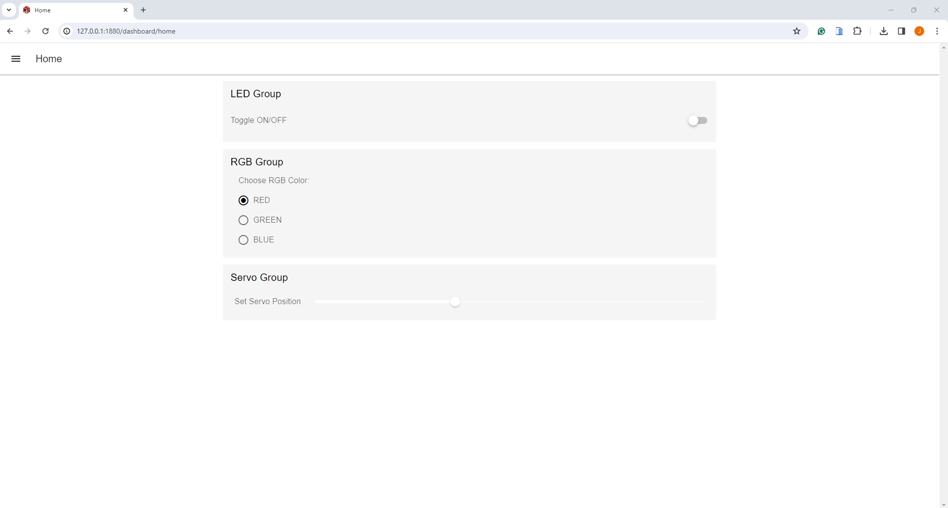
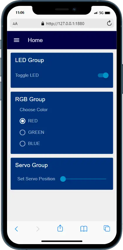
Using only the nodes above then it would generate a web user interface like the image below
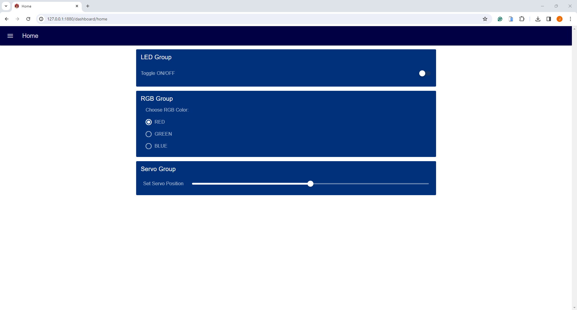
Or you can add colors to make it look like this.
And it even looks good when viewed on a mobile device. Cool right?!
A note about Node-Red Dashboard 2.0
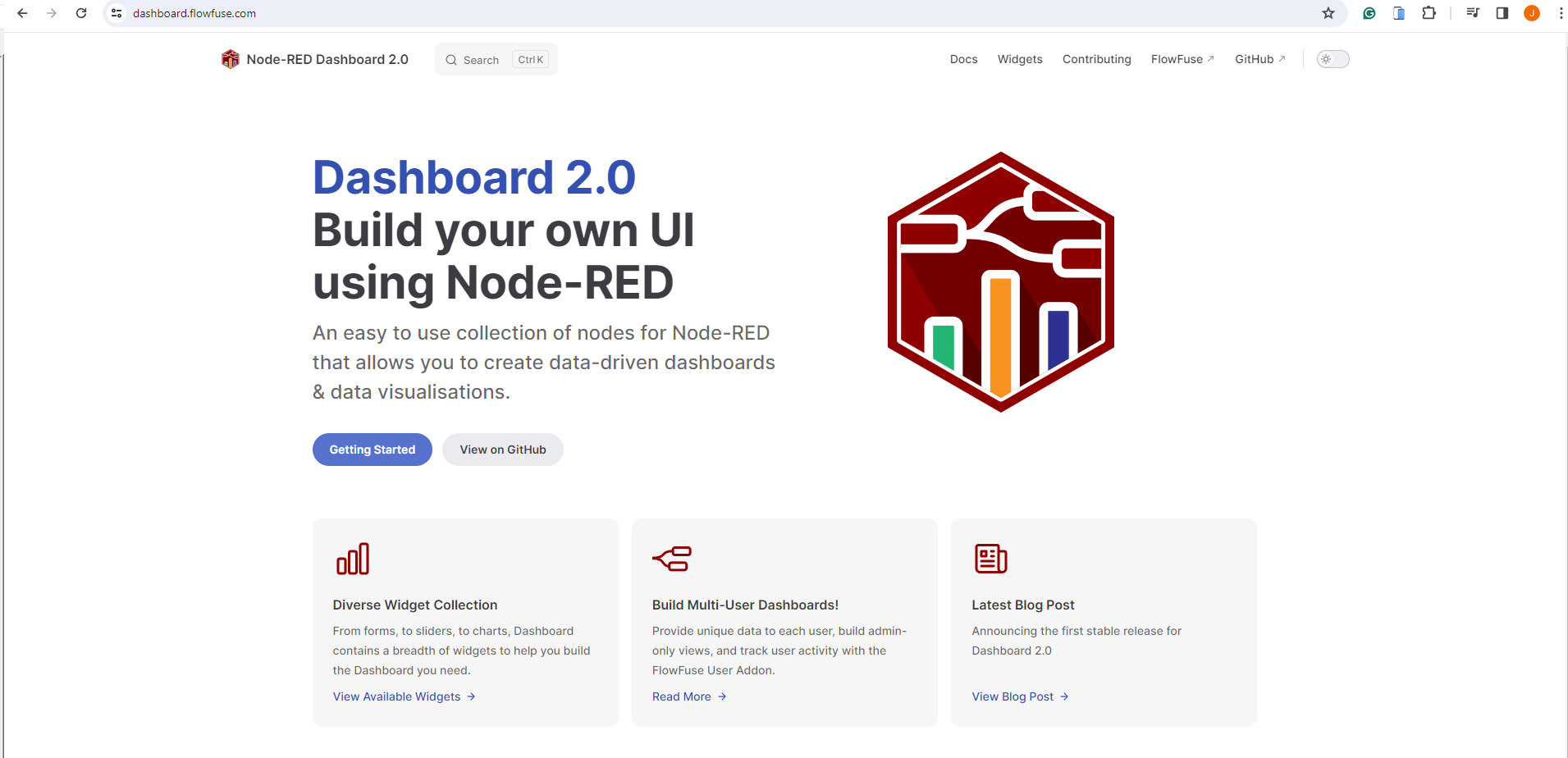
The original node-red-dashboard library is already dated and uses the old Angular V1. You can find the project here. Many of the tutorials are still referencing this library in building the web user interface of their project. I have used this in an old post that I have written entitled Node-Red – IoT Dashboard with Arduino – No Coding Required! One of the challenges that you would encounter in using this project is how to customize it to your liking and it has not received any major updates for several years.
Fortunately, FlowFuse released Dashboard 2.0 with an updated user interface similar to the original node-red-dashboard. In this, post, I will show you how easy it is to work with this new library and apply it to your IoT project with minimal code.
Note: Since this library is quite new and development is very active you may want to refer to the official documentation here always.
Prerequisites
A laptop or desktop workstation with sufficient memory, hard disk, and CPU is required to follow along with this post.
You need to have access to a working Node-Red environment either through a locally installed application on your laptop or your Raspberry Pi. If you need help on how to do this then please see below post I have written about it.
Related Posts:
How to install Node-Red (or Node Red) on a Windows environment?
How to install Node-Red on Raspberry Pi
Basic knowledge about the MQTT protocol and an MQTT server is also needed for this project. I have used the Mosquitto MQTT server for this purpose and have installed it on my Windows 11 machine.
Related Posts:
Install Mosquitto MQTT Windows
How to test MQTT using MQTTX?
I have used PlatformIO IDE in developing this project but you can use the Arduino IDE if you are more comfortable with it. If you would like to learn how to use the PlatformIO IDE then you can follow along with my earlier post about PlatformIO Tutorial for Arduino Development.
Parts/Components Required
The following are the parts and components required to follow along with this post.
- Windows 11 Laptop – Amazon | AliExpress
- or Raspberry Pi 5 Kit – Amazon | AliExpress
- ESP32 – Amazon | AliExpress
- RGB LED Module – Amazon | AliExpress
- SG90 Servo – Amazon | AliExpress
- or MG90 – Amazon | AliExpress
- LED – Amazon | AliExpress
- Resistors (220 Ohms) – Amazon | AliExpress
- Capacitors (450 uF) – Amazon | AliExpress
- Bench Power Supply – Amazon | AliExpress
- Breadboard – Amazon | AliExpress
- Connecting Wires – Amazon | AliExpress
Disclosure: These are affiliate links and I will earn small commissions to support my site when you buy through these links.
Design
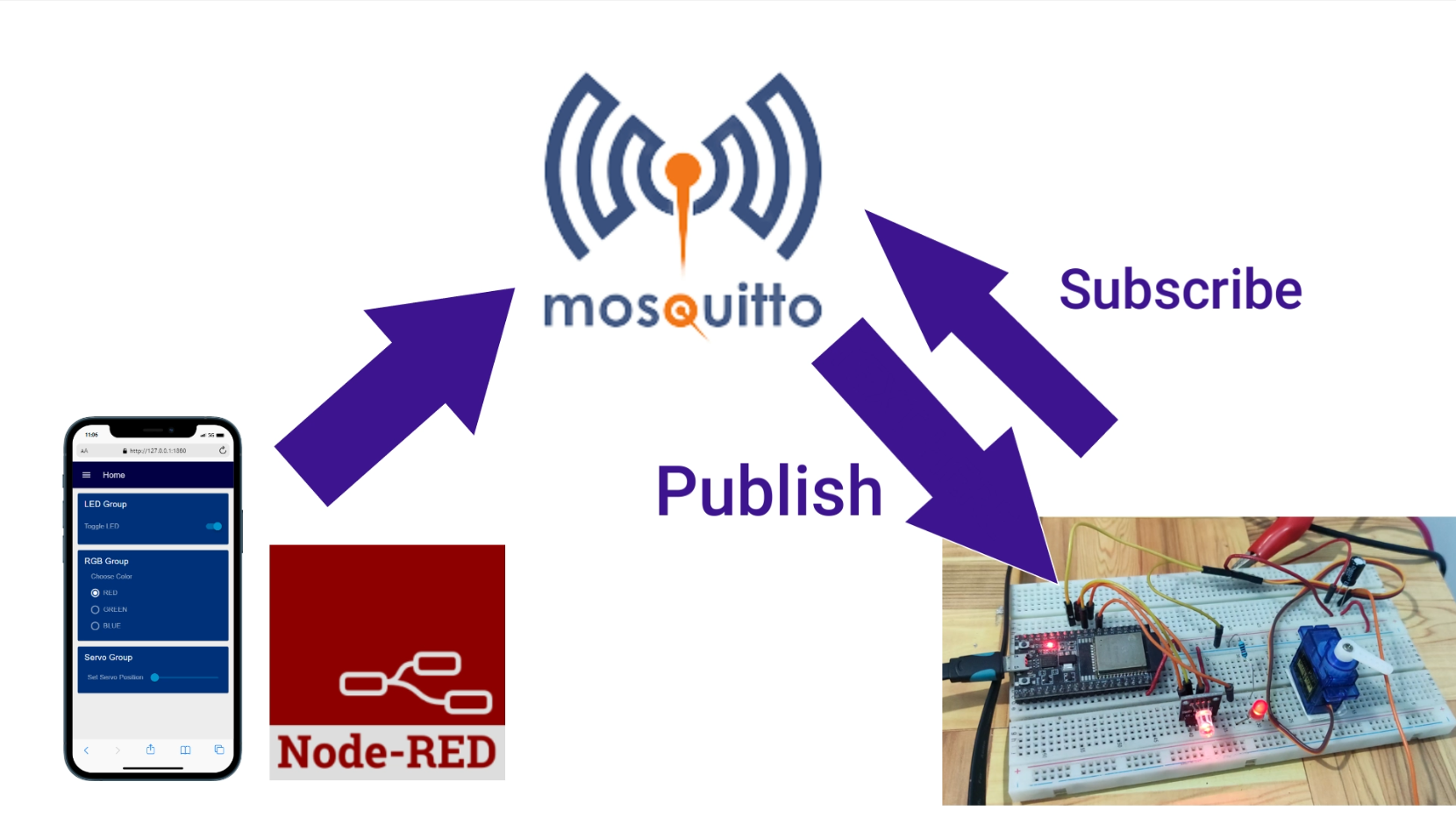
The above image will show you the overall design of this project. I have created my web application using the Node-Red tool with the help of the new Dashboard 2.0 package or library.
The web application communicates with the Mosquitto MQTT broker. My Arduino electronic circuit then subscribed to the specific topic to control the components connected to it. When a user interacts with the user interface of my project then it publishes a message on a specific topic to my Mosquitto MQTT broker. The Mosquitto MQTT broker will notify my Arduino electronic circuit to change the state of the components attached to it.
This is how we could control our Arduino electronic circuit remotely through your web interface.
Wiring/Schematic
The below image will show you the wiring and schematic that I have used for this particular project.
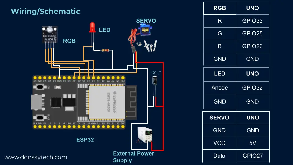
My SG90 servo is making a weird jitter movement so to fix the issue, I have added a 470uF capacitor and attached it to an external power supply. After doing this, the movement becomes smooth.
Code
Node-Red Flow
The complete flow that I have written can be found on my GitHub repository so you may want to check out and import the JSON file into your own local Node-Red server.
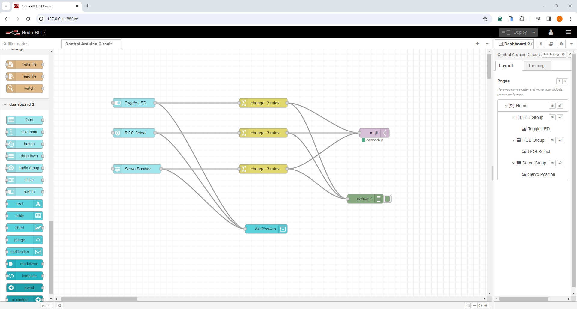
Below is how I have re-arranged the nodes and some configurations needed. You may want to view the video I wrote on my YouTube channel if you want a step-by-step guide and why I have chosen the following nodes.
As you can see, I have just dragged 3 Node-Red Dashboard 2.0 nodes to create a toggle switch, radio buttons, and slider component. Using these three nodes, I could create the required user interface that I like.
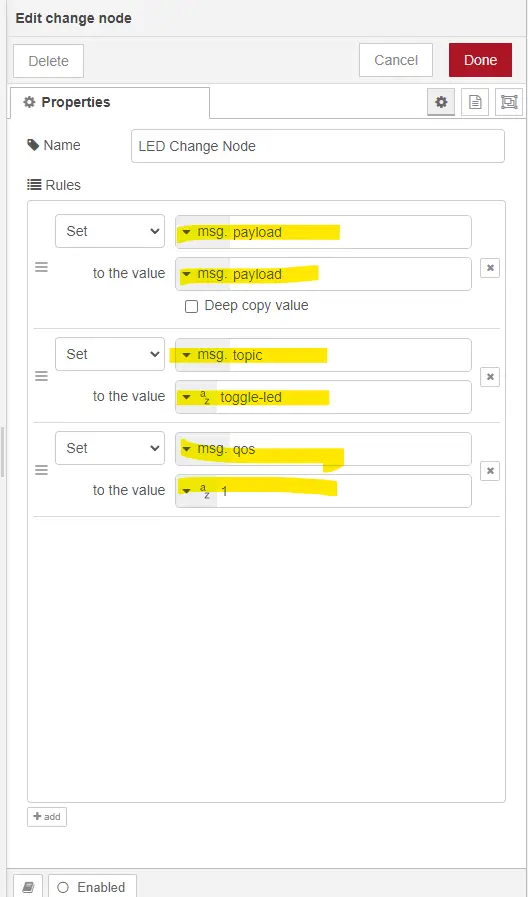
I only have one MQTT Out node here so I have used 3 separate Change Nodes to set the different topics, QOS, and payload.
I have only dragged these nodes into my flows and configured them accordingly and I was able to create a Web User interface that will allow me to control my Arduino electronic circuits. So even if you don’t know HTML/CSS/Javascript and by just using Node-Red then you could come up with your own IoT application.
ESP32 Arduino Program
Setup the project
The Arduino program that will receive MQTT messages from our Node-Red dashboard is also available on my GitHub repository. Please follow my earlier post about How to download a GitHub file, folder, or project if you want to have a local copy on your workstation.
You can also use Git to download the project by following the below command.
git clone https://github.com/donskytech/platformio-projects.git
cd esp32-projects
/esp32-mqtt-node-red-control/
Open the project in Visual Studio Code once you are done downloading it.
Libraries used in this project
I have used the following two libraries in developing this project and they are available in the platform.ini file of the project
[env:esp32dev]
platform = espressif32
board = esp32dev
framework = arduino
lib_deps =
	knolleary/PubSubClient@^2.8
madhephaestus/ESP32Servo@^1.1.2- pubsubclient – for MQTT message exchange
- ESP32Servo – for servo control
Complete Code
The complete Arduino code for our Node-Red Dashboard-controlled circuit is shown below.
#include <Arduino.h>
#include <ESP32Servo.h>
#include <WiFi.h>
#include <PubSubClient.h>

// Update these with your Wi-Fi and MQTT broker details
const char *ssid = "<CHANGE_TO_YOUR_WIFI_SSID>";
const char *password = "<CHANGE_TO_YOUR_WIFI_PASSWORD>";
const char *mqtt_server = "<CHANGE_TO_YOUR_MQTT_SERVER_IP>";

WiFiClient espClient;
PubSubClient client(espClient);

const char *mqttToggleLEDTopic = "toggle-led";
const char *mqttRGBColorSetTopic = "rgb-color-set";
const char *mqttServoPositionSetTopic = "servo-position-set";

// LED PIN Setup
const int LED_PIN = 32;

// RGB LED PIN Setup
const int redPin = 33;
const int greenPin = 25;
const int bluePin = 26;

// Servo PinSetup
int const servoPin = 27;
Servo servoMotor;
int pos = 0;

//  Forward Declaration
void processMessage(const char *topic, const char *message);
void moveServo(int position);
void setupWifi();
void mqttCallback(char *topic, byte *payload, unsigned int length);
void reconnect();
void handleLedMessage(String payload);
void handleRgbMessage(String payload);
void handleServoMessage(String payload);

void setup()
{
  Serial.begin(9600);
  // Setup WiFi connection details
  setupWifi();
  // Setup MQTT Connection
  client.setServer(mqtt_server, 1883);
  client.setCallback(mqttCallback);

  // Initialize other setup tasks if needed
  pinMode(LED_PIN, OUTPUT);
  // RGB LED
  pinMode(redPin, OUTPUT);
  pinMode(greenPin, OUTPUT);
  pinMode(bluePin, OUTPUT);

	// Allow allocation of all timers
	ESP32PWM::allocateTimer(0);
	ESP32PWM::allocateTimer(1);
	ESP32PWM::allocateTimer(2);
	ESP32PWM::allocateTimer(3);
  servoMotor.setPeriodHertz(50);           // standard 50 hz servo
  servoMotor.attach(servoPin, 500, 2450); // attaches the servo on pin 18 to the servo object
  moveServo(0);

}

void loop()
{
  if (!client.connected())
  {
    reconnect();
  }
  client.loop();

}

void setupWifi()
{
  delay(10);
  Serial.println();
  Serial.print("Connecting to ");
  Serial.println(ssid);

  WiFi.begin(ssid, password);

  while (WiFi.status() != WL_CONNECTED)
  {
    delay(500);
    Serial.print(".");
  }

  Serial.println("");
  Serial.println("WiFi connected");
  Serial.println("IP address: ");
  Serial.println(WiFi.localIP());
}

void mqttCallback(char *topic, byte *payload, unsigned int length)
{

  String payloadStr = "";
  for (int i = 0; i < length; i++)
  {
    payloadStr += (char)payload[i];
  }

  Serial.print("Received message on topic '");
  Serial.print(topic);
  Serial.print("': ");
  Serial.println(payloadStr);

  if (strcmp(topic, mqttToggleLEDTopic) == 0)
  {
    handleLedMessage(payloadStr);
  }
  else if (strcmp(topic, mqttRGBColorSetTopic) == 0)
  {
    handleRgbMessage(payloadStr);
  }
  else if (strcmp(topic, mqttServoPositionSetTopic) == 0)
  {
    handleServoMessage(payloadStr);
  }
}

void reconnect()
{
  while (!client.connected())
  {
    Serial.print("Attempting MQTT connection...");
    if (client.connect("ESP32Client"))
    {
      Serial.println("connected");
      client.subscribe(mqttToggleLEDTopic);
      client.subscribe(mqttRGBColorSetTopic);
      client.subscribe(mqttServoPositionSetTopic);
    }
    else
    {
      Serial.print("failed, rc=");
      Serial.print(client.state());
      Serial.println(" try again in 5 seconds");
      delay(5000);
    }
  }
}

void handleLedMessage(String payload)
{
  if (payload.equals("true"))
  {
    digitalWrite(LED_PIN, HIGH);
  }
  else if (payload.equals("false"))
  {
    digitalWrite(LED_PIN, LOW);
  }
}

void handleRgbMessage(String payload)
{
  if (payload.equals("red"))
  {
    analogWrite(redPin, 255);
    analogWrite(greenPin, 0);
    analogWrite(bluePin, 0);
  }
  else if (payload.equals("green"))
  {
    analogWrite(redPin, 0);
    analogWrite(greenPin, 255);
    analogWrite(bluePin, 0);
  }
  else if (payload.equals("blue"))
  {
    analogWrite(redPin, 0);
    analogWrite(greenPin, 0);
    analogWrite(bluePin, 255);
  }
}

void handleServoMessage(String payload)
{
  int angle = payload.toInt();
  moveServo(angle);
}

void moveServo(int position)
{
  // Set the servo position
  servoMotor.write(position);

  // Wait for some time
  delay(20);
}
Let us run through the program line by line.
#include <Arduino.h>
#include <ESP32Servo.h>
#include <WiFi.h>
#include <PubSubClient.h>

// Update these with your Wi-Fi and MQTT broker details
const char *ssid = "<CHANGE_TO_YOUR_WIFI_SSID>";
const char *password = "<CHANGE_TO_YOUR_WIFI_PASSWORD>";
const char *mqtt_server = "<CHANGE_TO_YOUR_MQTT_SERVER_IP>";
First, we import the necessary header files needed by our project. Next, update also the ssid, password, and mqtt_server variables to match your setup.
WiFiClient espClient;
PubSubClient client(espClient);

const char *mqttToggleLEDTopic = "toggle-led";
const char *mqttRGBColorSetTopic = "rgb-color-set";
const char *mqttServoPositionSetTopic = "servo-position-set";
Create an instance of the PubSubClient class and set the name of the MQTT topics that we need to listen to. The following topics will be used by our Node-Red Dashboard application to send messages to our Arduino project.
// LED PIN Setup
const int LED_PIN = 32;

// RGB LED PIN Setup
const int redPin = 33;
const int greenPin = 25;
const int bluePin = 26;

// Servo PinSetup
int const servoPin = 27;
Servo servoMotor;
int pos = 0;
Declare the necessary pins where we have attached our LED, RGB LED, and servo motor.
//  Forward Declaration
void processMessage(const char *topic, const char *message);
void moveServo(int position);
void setupWifi();
void mqttCallback(char *topic, byte *payload, unsigned int length);
void reconnect();
void handleLedMessage(String payload);
void handleRgbMessage(String payload);
void handleServoMessage(String payload);
The functions above are forward declarations of the functions that we will be using later so that our program will compile.
void setup()
{
  Serial.begin(9600);
  // Setup WiFi connection details
  setupWifi();
  // Setup MQTT Connection
  client.setServer(mqtt_server, 1883);
  client.setCallback(mqttCallback);

  // Initialize other setup tasks if needed
  pinMode(LED_PIN, OUTPUT);
  // RGB LED
  pinMode(redPin, OUTPUT);
  pinMode(greenPin, OUTPUT);
  pinMode(bluePin, OUTPUT);

	// Allow allocation of all timers
	ESP32PWM::allocateTimer(0);
	ESP32PWM::allocateTimer(1);
	ESP32PWM::allocateTimer(2);
	ESP32PWM::allocateTimer(3);
  servoMotor.setPeriodHertz(50);           // standard 50 hz servo
  servoMotor.attach(servoPin, 500, 2450); // attaches the servo on pin 18 to the servo object
  moveServo(0);

}
In the function setup(), we do the following configuration steps:
- initialize the serial monitor baud rate
- setup the wifi connection
- setup the MQTT connection
- initialize the different pins connected to our components
- configure the servo motor and set it to the initial zero position
void loop()
{
  if (!client.connected())
  {
    reconnect();
  }
  client.loop();
}
The loop() function will continually check for MQTT connection and incoming messages.
void setupWifi()
{
  delay(10);
  Serial.println();
  Serial.print("Connecting to ");
  Serial.println(ssid);

  WiFi.begin(ssid, password);

  while (WiFi.status() != WL_CONNECTED)
  {
    delay(500);
    Serial.print(".");
  }

  Serial.println("");
  Serial.println("WiFi connected");
  Serial.println("IP address: ");
  Serial.println(WiFi.localIP());
}
We start connecting to our WiFi network using the code above. Take note of the IP Address of your ESP32 microcontroller.
void mqttCallback(char *topic, byte *payload, unsigned int length)
{

  String payloadStr = "";
  for (int i = 0; i < length; i++)
  {
    payloadStr += (char)payload[i];
  }

  Serial.print("Received message on topic '");
  Serial.print(topic);
  Serial.print("': ");
  Serial.println(payloadStr);

  if (strcmp(topic, mqttToggleLEDTopic) == 0)
  {
    handleLedMessage(payloadStr);
  }
  else if (strcmp(topic, mqttRGBColorSetTopic) == 0)
  {
    handleRgbMessage(payloadStr);
  }
  else if (strcmp(topic, mqttServoPositionSetTopic) == 0)
  {
    handleServoMessage(payloadStr);
  }
}

void reconnect()
{
  while (!client.connected())
  {
    Serial.print("Attempting MQTT connection...");
    if (client.connect("ESP32Client"))
    {
      Serial.println("connected");
      client.subscribe(mqttToggleLEDTopic);
      client.subscribe(mqttRGBColorSetTopic);
      client.subscribe(mqttServoPositionSetTopic);
    }
    else
    {
      Serial.print("failed, rc=");
      Serial.print(client.state());
      Serial.println(" try again in 5 seconds");
      delay(5000);
    }
  }
}
The two functions above are used to parse the MQTT messages received from our Node-Red dashboard and for reconnection purposes.
MQTT topics are inspected and the messages are extracted so that we can handle the lighting of our LEDs and servo movement using the functions handleLedMessage(), handleRgbMessage(), and handleServoMessage().
void handleLedMessage(String payload)
{
  if (payload.equals("true"))
  {
    digitalWrite(LED_PIN, HIGH);
  }
  else if (payload.equals("false"))
  {
    digitalWrite(LED_PIN, LOW);
  }
}

void handleRgbMessage(String payload)
{
  if (payload.equals("red"))
  {
    analogWrite(redPin, 255);
    analogWrite(greenPin, 0);
    analogWrite(bluePin, 0);
  }
  else if (payload.equals("green"))
  {
    analogWrite(redPin, 0);
    analogWrite(greenPin, 255);
    analogWrite(bluePin, 0);
  }
  else if (payload.equals("blue"))
  {
    analogWrite(redPin, 0);
    analogWrite(greenPin, 0);
    analogWrite(bluePin, 255);
  }
}

void handleServoMessage(String payload)
{
  int angle = payload.toInt();
  moveServo(angle);
}

void moveServo(int position)
{
  // Set the servo position
  servoMotor.write(position);

  // Wait for some time
  delay(20);
}
The functions above handle the turning on or off of our LED, changing the color of the RGB LED, and moving the servo motor to a specific position.
Wrap Up
In this post, I have shown you how you can take advantage of the low-code platform Node-Red to develop an IoT application with the help of the new FlowFuse Dashboard 2.0 package. For beginners, it would be easy to create these applications without the need to understand web development technologies such as HTML/CSS/Javascript.
I highly suggest that you watch the accompanying video as I have put together a step by step procedure on how I was able to come up with a working prototype of this project.
I hope you learned something. Happy exploring!
Read Next:
Node-Red – Display Arduino Sensor Readings through WebSocket
Node-Red – DHT11/DHT22 – Custom Weather Station Dashboard
Leave a Reply